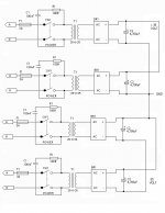
In the example shown, you'll be OK as you are paralleling at the outputs of the individual rectifiers. Obviously the load sharing will be a function of how well-matched the transformers are.
Paralleling separate transformers at the windings themselves is a bad idea, as they voltages will not match exactly, and you will get circulating current paths between the transformers, wasting power and heating up the transformers!
Paralleling separate transformers at the windings themselves is a bad idea, as they voltages will not match exactly, and you will get circulating current paths between the transformers, wasting power and heating up the transformers!
No problem with series connecting the outputs.
Are you connecting the primaries in parallel for 110V operation, or series connecting them for 220V? (If series connecting then you need to ensure that the load on each of the two transformers is equal).
Is Canada 110V or 220v for the normal single-phase domestic supply? I don't know how far you ape your larger neighbour to the south, or follow the rest of the world")
Are you connecting the primaries in parallel for 110V operation, or series connecting them for 220V? (If series connecting then you need to ensure that the load on each of the two transformers is equal).
Is Canada 110V or 220v for the normal single-phase domestic supply? I don't know how far you ape your larger neighbour to the south, or follow the rest of the world
serial connection
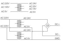
Once I had questioned from a guy who just start the gainclone relating the serial conection of two 0,24V EI transformer.
Because it has no centertap. He wanted to use two of them.
I suggest that 'A' trnasformer 24V go to "+" of the bridge
'A' transformer 0V and the 'B'transformer 24V goto 'GND'
"B" transformer 0V goto "-"of the bridge.
However he connect it as attached file and
finally he get +30,0,-30V with no problem.
Will it be OK?
Attachments
Ouroboros said:No problem with series connecting the outputs.
Are you connecting the primaries in parallel for 110V operation, or series connecting them for 220V? (If series connecting then you need to ensure that the load on each of the two transformers is equal).
Is Canada 110V or 220v for the normal single-phase domestic supply? I don't know how far you ape your larger neighbour to the south, or follow the rest of the world
Canada is 110V (getting 120 from the outlet). So I will be connecting the primaries in parallel.
thanks
Re: serial connection
Not sure if it will work. (I am assuming you want 24-0-24 Ac lines to feed your bridge or +33-0-(-)33 vdc rectified)
If the two primaries are in paralell, the voltages in the secondaries will be the same. If thats the case the voltage of the two 24v taps will be the same and you will not get full wave rectification after the bridges.
In order to get full wave (dual rails) voltages, you need to connect the 0v of trafo 1 to the 24v of trafo 2. This will become your gnd.
Then feed the bridge rectifier with the 24v of trafo 1 and 0v of trafo2. This will give you +33vdc and -33vdc after the rectifier.
hope this is what you were looking for...
thkim15 said:Once I had questioned from a guy who just start the gainclone relating the serial conection of two 0,24V EI transformer.
Because it has no centertap. He wanted to use two of them.
I suggest that 'A' trnasformer 24V go to "+" of the bridge
'A' transformer 0V and the 'B'transformer 24V goto 'GND'
"B" transformer 0V goto "-"of the bridge.
However he connect it as attached file and
finally he get +30,0,-30V with no problem.
Will it be OK?
Not sure if it will work. (I am assuming you want 24-0-24 Ac lines to feed your bridge or +33-0-(-)33 vdc rectified)
If the two primaries are in paralell, the voltages in the secondaries will be the same. If thats the case the voltage of the two 24v taps will be the same and you will not get full wave rectification after the bridges.
In order to get full wave (dual rails) voltages, you need to connect the 0v of trafo 1 to the 24v of trafo 2. This will become your gnd.
Then feed the bridge rectifier with the 24v of trafo 1 and 0v of trafo2. This will give you +33vdc and -33vdc after the rectifier.
hope this is what you were looking for...
Re: serial connection
I would connect them after the bridge rectifiers. That way you have the "A" + as the +24, the A - and B+ connected as the ground, and the B- as the -24.
And on the original topic of paralleling transformers, I'm using 8 dual secondary transformers (originally center tap, but modified to dual secondary) in parallel, but connecting them AFTER the bridge rectifiers.
thkim15 said:Once I had questioned from a guy who just start the gainclone relating the serial conection of two 0,24V EI transformer.
Because it has no centertap. He wanted to use two of them.
I suggest that 'A' trnasformer 24V go to "+" of the bridge
'A' transformer 0V and the 'B'transformer 24V goto 'GND'
"B" transformer 0V goto "-"of the bridge.
However he connect it as attached file and
finally he get +30,0,-30V with no problem.
Will it be OK?
I would connect them after the bridge rectifiers. That way you have the "A" + as the +24, the A - and B+ connected as the ground, and the B- as the -24.
And on the original topic of paralleling transformers, I'm using 8 dual secondary transformers (originally center tap, but modified to dual secondary) in parallel, but connecting them AFTER the bridge rectifiers.
- Status
- This old topic is closed. If you want to reopen this topic, contact a moderator using the "Report Post" button.
- Home
- Amplifiers
- Chip Amps
- Paralleling Transformers