Final Installation
In my original post in this thread, I mentioned that I was building this amplifier to replace an AVR that I was using to amplify the outputs from my miniDSP's digital crossovers to drive my 3-way speakers. This means that the AVR had six RCA interconnect cables as inputs from the miniDSP and twelve banana plug speaker cables as outputs going to a 2-gang binding post wall plate. That had been a lot of cables to make up. From the other side of the wall plate, I had run lots of twisted pair plenum-rated 14 AWG speaker cables under the floor and then up to the back of a pair of SpeakOn 8-pole wall sockets behind my speakers. A pair of short 8-pole SpeakOn cables with plugs on each end made the short journey across the floor to similar SpeakOn sockets in my speakers. This kept the floor reasonably tidy.
Having that many cables in the back of an AVR made the probability of a miss-connection quite likely, and was something that my wife would never be able to deal with. Of course, AVRs bristle with connectors and have labelling that is impossible to read when you're peering over the top and trying to read labels which are upside down and obscured by the connectors above.
My new amplifier would still have six interconnect inputs, but now I had more real estate available for them, and the dozen speaker outputs was reduced to two SpeakOn outputs. Simple is usually better.
Here are the rear panels for my AVR and my new dual-purpose amplifier:


In case you're wondering, the woofer XLR sockets are black to differentiate them from the others. When the amp is used for two-channel stereo with conventional speakers with passive crossovers, I have a pair of RCA-to-XLR interconnect cables with matching black XLR plugs to reduce the possibility of error (you may recall that "conventional mode" uses only the woofer amplification modules, and thus uses only the woofer XLR inputs. In this mode, the speaker output is via the adjacent binding posts).
The miniDSP designers must have been concerned about the amount of real estate that eight XLR sockets would occupy too, so they use a pair of 12-position Phoenix terminal blocks instead. The mating plugs are included with the 4x10HD, so you needn't buy a pair like I did.
Here's the back of my miniDSP:

There are two terminal blocks, one above the other. Each one accommodates four channels, with three wires per channel (ground, positive, and negative). For reasons best known to themselves, the designers numbered the top terminal block for channels 2, 4, 6, and 8 and the bottom block for channels 1, 3, 5, and 7. Yet another opportunity for mistakes! One of the miniDSP's greatest weaknesses, in my opinion, is its rather poor usability, although it works very well once you've got past that.
Here are my "old" RCA cables from the AVR to the wall plate together with their new SpeakOn replacements:

Here's the new wall plate (a big improvement):

Just need to touch up the wall paint.
I mentioned previously that SpeakOn connectors and cables are quite expensive. Furthermore, the cable can be relatively difficult to find. In order to get from the amplifier's output sockets to my wall plate, I bought a ready-made 3 metre (10 feet) cable, cut it in half, and fitted plugs to the cut ends. I bought four sockets - two for the amp and two to put in a blank wall plate. The total cost for this was about C$190 before taxes (this is in Canadian dollars, so do your own conversion). The alternative would have involved twelve binding posts for the amp, a wall plate with twelve more, two dozen of your favourite banana plugs, and 36 metres (120 feet) of your favourite speaker cable, which adds up to more than the SpeakOn gear. Of course, I already had all of this, but the point I'm making might help you with a similar decision.
The disadvantages of XLRs and SpeakOns are that they are more fiddly to wire up and there's more opportunity for error (which I took great advantage of), and they need more depth - allow about 150mm (6") behind your amp for SpeakOn cables). On the other hand, as I have said previously, suffer once but enjoy the benefit forever.
Just to make life more complicated, I had previously run wires for eight channels under my floor and wired my SpeakOns to my speakers similarly in anticipation of building an eight-channel amplifier to accommodate my dual woofers. The decision to build six channels instead meant that I had to make a few changes to the wiring under the floor and inside my speakers to accommodate the change.
All this took several days.
Next: "first sound".
In my original post in this thread, I mentioned that I was building this amplifier to replace an AVR that I was using to amplify the outputs from my miniDSP's digital crossovers to drive my 3-way speakers. This means that the AVR had six RCA interconnect cables as inputs from the miniDSP and twelve banana plug speaker cables as outputs going to a 2-gang binding post wall plate. That had been a lot of cables to make up. From the other side of the wall plate, I had run lots of twisted pair plenum-rated 14 AWG speaker cables under the floor and then up to the back of a pair of SpeakOn 8-pole wall sockets behind my speakers. A pair of short 8-pole SpeakOn cables with plugs on each end made the short journey across the floor to similar SpeakOn sockets in my speakers. This kept the floor reasonably tidy.
Having that many cables in the back of an AVR made the probability of a miss-connection quite likely, and was something that my wife would never be able to deal with. Of course, AVRs bristle with connectors and have labelling that is impossible to read when you're peering over the top and trying to read labels which are upside down and obscured by the connectors above.
My new amplifier would still have six interconnect inputs, but now I had more real estate available for them, and the dozen speaker outputs was reduced to two SpeakOn outputs. Simple is usually better.
Here are the rear panels for my AVR and my new dual-purpose amplifier:
In case you're wondering, the woofer XLR sockets are black to differentiate them from the others. When the amp is used for two-channel stereo with conventional speakers with passive crossovers, I have a pair of RCA-to-XLR interconnect cables with matching black XLR plugs to reduce the possibility of error (you may recall that "conventional mode" uses only the woofer amplification modules, and thus uses only the woofer XLR inputs. In this mode, the speaker output is via the adjacent binding posts).
The miniDSP designers must have been concerned about the amount of real estate that eight XLR sockets would occupy too, so they use a pair of 12-position Phoenix terminal blocks instead. The mating plugs are included with the 4x10HD, so you needn't buy a pair like I did.
Here's the back of my miniDSP:
There are two terminal blocks, one above the other. Each one accommodates four channels, with three wires per channel (ground, positive, and negative). For reasons best known to themselves, the designers numbered the top terminal block for channels 2, 4, 6, and 8 and the bottom block for channels 1, 3, 5, and 7. Yet another opportunity for mistakes! One of the miniDSP's greatest weaknesses, in my opinion, is its rather poor usability, although it works very well once you've got past that.
Here are my "old" RCA cables from the AVR to the wall plate together with their new SpeakOn replacements:
Here's the new wall plate (a big improvement):
Just need to touch up the wall paint.
I mentioned previously that SpeakOn connectors and cables are quite expensive. Furthermore, the cable can be relatively difficult to find. In order to get from the amplifier's output sockets to my wall plate, I bought a ready-made 3 metre (10 feet) cable, cut it in half, and fitted plugs to the cut ends. I bought four sockets - two for the amp and two to put in a blank wall plate. The total cost for this was about C$190 before taxes (this is in Canadian dollars, so do your own conversion). The alternative would have involved twelve binding posts for the amp, a wall plate with twelve more, two dozen of your favourite banana plugs, and 36 metres (120 feet) of your favourite speaker cable, which adds up to more than the SpeakOn gear. Of course, I already had all of this, but the point I'm making might help you with a similar decision.
The disadvantages of XLRs and SpeakOns are that they are more fiddly to wire up and there's more opportunity for error (which I took great advantage of), and they need more depth - allow about 150mm (6") behind your amp for SpeakOn cables). On the other hand, as I have said previously, suffer once but enjoy the benefit forever.
Just to make life more complicated, I had previously run wires for eight channels under my floor and wired my SpeakOns to my speakers similarly in anticipation of building an eight-channel amplifier to accommodate my dual woofers. The decision to build six channels instead meant that I had to make a few changes to the wiring under the floor and inside my speakers to accommodate the change.
All this took several days.
Next: "first sound".
While I’ve yet to actually hear it, miniDSP/Modulus combination came directly from a conversation several years ago with Tom.
When circumstances permit, I must plan a road trip that includes a stop in Neurochrome country.
When circumstances permit, you'll be able to hear it ten minutes up the road!
While I’ve yet to actually hear it, miniDSP/Modulus combination came directly from a conversation several years ago with Tom.
When circumstances permit, I must plan a road trip that includes a stop in Neurochrome country.
You're always welcome.
I'm also hoping for a trip west sometime this year. One thought I've had is to drive to Denver for RMAF in early October, then San Francisco for BAF the following weekend, cruise north through Portland and Seattle to visit friends there. I'd be next door to you then... Swinging by would be easy. It would be nice with a taste of island life before heading home. That's a long trip, though. "Only 6500 km..."
")

Tom
Last edited:
I don’t think a few thousand km is all that much of an issue for Tom; he’s made similar road trips before, including layovers on the island. But two audio fests such as Rocky Mountain and Burning Amp in a single week might be a bit much of a strain on the digestive system and wallets if some of us seniors.
When circumstances permit, you'll be able to hear it ten minutes up the road!
Several years of recent RAM have been purged from my on-board cache and contact list - is it an Excelsior Rd address I’d be looking for?
All said, a very well conceived and executed plan.
First Sound
When astrophysicists build a new telescope, they refer to the first time that they use it for imaging as "first light". I've always liked this term, so I decided to adopt and adapt it for my amplifier.
With all the many changes that I had to make to my wiring in order to integrate my new amplifier with the rest of my system, I was concerned that I might have a few problems getting it to work. This turned out to be a pretty good assumption. With everything turned on and my Squeezebox streaming away, the silence was deafening. At least there was no smoke. After correcting an error with one of the input XLRs and a bit of miscellaneous fiddling, I managed to get some fairly unpleasant sound from the midrange drivers.
As I've mentioned previously, the difficulty with specialised stuff like active crossovers and multichannel amplifiers is that it's not easy to switch components in and out for test purposes. Fortunately, I had built this amp as a dual-purpose amplifier, so I ran a couple of lengths of speaker cable across the floor to my "conventional" speakers and tried the amp in that mode. Same result. This seemed to eliminate all the wiring downstream of the amplifier.
After taking a break and practising my swearing, I realised that I had the two output plugs in the back of the miniDSP in the wrong sockets. It was mostly good luck that I hadn't sent a woofer signal to a tweeter, but no damage was done except to the self-esteem of the builder. Once the plugs were in the right holes, normal service was restored. I even remembered to reduce the attenuation of the midrange in the miniDSP's software to compensate for the reduced gain of the midrange Modulus-86 amplifiers (eventually).
I went immediately to a few of my favourite demo tracks and was not disappointed. I won't descend into audio-drivel and rattle on about lifting veils or getting to "the next level" (wherever that is), but I will say this: every time I make some kind of significant change to my system, I can't imagine how the resulting sound could ever be improved on . . . until it is. Moving to digital crossovers brought a major improvement in clarity and imaging; this amplifier has taken that further. That's about as much as I'm going to say until I've spent a fair amount of time allowing my brain to adjust to this amp.
Next: next steps.
Next Steps
Since I'm an inveterate experimenter and fiddler, I already have a couple of interesting tests in mind.
I still have my AKSA amplifier and Dennis Murphy 3-way speakers in the same room, so it's going to be very easy to do a side-by-side comparison of two amplifiers through the same speakers (using my new amp in "conventional mode"). I'm pretty sure about what I'll hear, because I did something similar with Tom Christiansen's demo Modulus-686 amplifier a couple of years ago, but I won't be able to resist - plus I have no time-limit on doing the comparison now, so it should be easier to spot the differences once my brain has had a chance to get used to the nuances.
Thinking longer term, I can't help wondering to what extent the construction of the filters in my digital crossovers were influenced by whatever noise and distortion was present in my system when I constructed them. It would be very interesting to revisit them now that my speakers are receiving a cleaner signal. Furthermore, I think I can drag all my gear into a large open space outside and do some measurements with much longer times to first reflections and thus get some meaningful data at lower frequencies. I think this latter point is more compelling than the former, but again I won't be able to resist. I'll need to figure out a way to suspend my microphone, and I'll need still, dry weather and lots of time. Unfortunately, I can't see this happening soon.
Oh, I can't believe that I've only just thought of this . . . I designed this amp so that I can run it with "conventional" speakers using (typically) a pair of RCA-to-XLR input cables from some kind of volume-controlled pre-amp to the woofer inputs on the amp, and connecting the speakers via the amp's binding posts (with the SpeakOn outputs disconnected). I've just realised that I can configure a preset on my miniDSP to route a full-range digital input signal through its internal DACs to the woofer outputs without any filtering or EQ. In other words, I can use the miniDSP as nothing more than a DAC, thus enabling me to A/B speakers without any changes in the upstream hardware. I can see many happy hours ahead.
Next and final post: conclusions.
Final Thoughts
This has been a terrific project. I set out to build an amplifier that would meet very specific requirements and have done just that. The project took rather longer than I anticipated and came in about 50% over budget, but the result is superb. The sound is crystal-clear and the amp is dead quiet - zero hum at zero attenuation.
The design is quite complex, as you might expect for a six-channel amplifier, and all the more so for using two different types of amplifier modules together with XLR inputs and SpeakOn outputs. It's probably not a first project for a beginner. I'm far from being an expert, but I have built a variety of projects over the years and I have a decent workshop too. I reckon that I can build almost anything as long as it comes with a good instruction manual, but having the designer just an email away is excellent back-up. If you are interested in building a Neurochrome amp - which I can highly recommend - the website will step you through the options for amplifiers to suit all budgets and levels of competence.
All power amps are essentially boxes with or without switches and lights on the front. Here's how mine turned out (the photograph doesn't really do it justice):

The Dissipante chassis looks very attractive with its striking faceplate and wavy heat sinks, but its simple design speaks to the desire to drive manufacturing costs down - the only remotely complicated piece of metal fabrication being the corner brackets. In consequence, the sheet metal panels - the top, bottom, and rear - are flat and lack stiffness. The weight of the transformer is sufficient to make the bottom sag, while the rear panel deflects when its screws are tightened or if you push or pull hard on a connector or the power plug. The simple fix for the bottom is either a pad under the head of the transformer mounting bolt or a fifth foot (I've used a felt pad for now). The rear panel needs either a supporting bracket or a turned edge to add stiffness. I mentioned earlier that I had to shim the rear panel with a washer between the panel and the corner brackets, because the latter were slightly too short. Nonetheless, the end result is modestly spectacular - especially for a piece of home-built gear.
Wiring certainly presented its challenges, although it became a lot easier once I had decided on a final arrangement. The XLRs and SpeakOns needed a lot of concentration to get right, and even then I still made mistakes. I have quite good spatial skills, but evidently not good enough! In my defence, I might add that I've been running an annual grey-cell deficit for many years now, so I'm sure that most of you would do better. Then there's the miniDSP: why would anyone use one output connector for channels 2, 4, 6, and 8, and put it above the other connector which has channels 1, 3, 5, and 7? I suppose it's better than assigning them at random, but only just.
I used solder with water-soluble flux for the first time on this project and, frankly, I didn't like it (this opinion is based on a single brand). It does clean up easily with warm water, but then I don't find using isopropyl alcohol much of a chore anyway. Once I'd finished populating the boards, I reverted to my usual solder, which I think flows better.
There are several design decisions that I'm particularly thankful for. One is using socket cap screws in most of the hard-to-reach places, and another is tapping the mounting holes in the rear panel. Both helped save my sanity every time I needed to assemble or disassemble something, which was often. If I were to do this again, I'd replace all the Dissipante corner bracket screws with socket caps instead of just the front and rear panel screws. I love the openness that comes from cantilevering the modules off the heat sinks without using big pillars or bottom-mounted brackets. I'm also thankful that I had learned the basics of Sketchup; being able to examine a number of different three-dimensional layouts was invaluable - especially when space started to get tight.
Would I do this again? Well, I have no regrets so far and I'm only just starting to "bond" with the sound of my new amp. If I were to do it again, there's not much that I would change. I would certainly be more careful about getting the Modulus-86 amps at the right height to ease the congestion around the SpeakOn terminals, and I would probably move the rear-most pair forwards 5 mm to provide a little more space around the binding posts. I would look more closely at using Nylon standoffs instead of screws and spacers for mounting the amps to their brackets (there were several reasons why I didn't use them). I would probably reduce the 2.5 mm holes I drilled in the front panel to 1.5 mm - the red LEDs are quite tolerable, but just a little too bright for my taste, although I am getting used to them. I thought I would change the red to green to match my on/off switch, but my wife quite likes it the way it is - she says it's "Christmassy". I would also take the time to source some push-on connectors for the SpeakOn terminals - I prefer the permanence of soldering, but soldering 8-pole SpeakOn sockets tries my patience too much. These are all fine details.
Finally, I must thank Tom Christiansen of Neurochrome for his patience in helping me to take this project from the germ of an idea through to a successful conclusion. For anyone with a suspicious mind (and that's a good thing to have these days), I have no affiliation with Neurochrome and I paid full retail prices for everything I bought. Thanks also to any of you who made it through this entire thread from start to finish; it turned out to be much longer than I anticipated - well done!
Em
This has been a terrific project. I set out to build an amplifier that would meet very specific requirements and have done just that. The project took rather longer than I anticipated and came in about 50% over budget, but the result is superb. The sound is crystal-clear and the amp is dead quiet - zero hum at zero attenuation.
The design is quite complex, as you might expect for a six-channel amplifier, and all the more so for using two different types of amplifier modules together with XLR inputs and SpeakOn outputs. It's probably not a first project for a beginner. I'm far from being an expert, but I have built a variety of projects over the years and I have a decent workshop too. I reckon that I can build almost anything as long as it comes with a good instruction manual, but having the designer just an email away is excellent back-up. If you are interested in building a Neurochrome amp - which I can highly recommend - the website will step you through the options for amplifiers to suit all budgets and levels of competence.
All power amps are essentially boxes with or without switches and lights on the front. Here's how mine turned out (the photograph doesn't really do it justice):
The Dissipante chassis looks very attractive with its striking faceplate and wavy heat sinks, but its simple design speaks to the desire to drive manufacturing costs down - the only remotely complicated piece of metal fabrication being the corner brackets. In consequence, the sheet metal panels - the top, bottom, and rear - are flat and lack stiffness. The weight of the transformer is sufficient to make the bottom sag, while the rear panel deflects when its screws are tightened or if you push or pull hard on a connector or the power plug. The simple fix for the bottom is either a pad under the head of the transformer mounting bolt or a fifth foot (I've used a felt pad for now). The rear panel needs either a supporting bracket or a turned edge to add stiffness. I mentioned earlier that I had to shim the rear panel with a washer between the panel and the corner brackets, because the latter were slightly too short. Nonetheless, the end result is modestly spectacular - especially for a piece of home-built gear.
Wiring certainly presented its challenges, although it became a lot easier once I had decided on a final arrangement. The XLRs and SpeakOns needed a lot of concentration to get right, and even then I still made mistakes. I have quite good spatial skills, but evidently not good enough! In my defence, I might add that I've been running an annual grey-cell deficit for many years now, so I'm sure that most of you would do better. Then there's the miniDSP: why would anyone use one output connector for channels 2, 4, 6, and 8, and put it above the other connector which has channels 1, 3, 5, and 7? I suppose it's better than assigning them at random, but only just.
I used solder with water-soluble flux for the first time on this project and, frankly, I didn't like it (this opinion is based on a single brand). It does clean up easily with warm water, but then I don't find using isopropyl alcohol much of a chore anyway. Once I'd finished populating the boards, I reverted to my usual solder, which I think flows better.
There are several design decisions that I'm particularly thankful for. One is using socket cap screws in most of the hard-to-reach places, and another is tapping the mounting holes in the rear panel. Both helped save my sanity every time I needed to assemble or disassemble something, which was often. If I were to do this again, I'd replace all the Dissipante corner bracket screws with socket caps instead of just the front and rear panel screws. I love the openness that comes from cantilevering the modules off the heat sinks without using big pillars or bottom-mounted brackets. I'm also thankful that I had learned the basics of Sketchup; being able to examine a number of different three-dimensional layouts was invaluable - especially when space started to get tight.
Would I do this again? Well, I have no regrets so far and I'm only just starting to "bond" with the sound of my new amp. If I were to do it again, there's not much that I would change. I would certainly be more careful about getting the Modulus-86 amps at the right height to ease the congestion around the SpeakOn terminals, and I would probably move the rear-most pair forwards 5 mm to provide a little more space around the binding posts. I would look more closely at using Nylon standoffs instead of screws and spacers for mounting the amps to their brackets (there were several reasons why I didn't use them). I would probably reduce the 2.5 mm holes I drilled in the front panel to 1.5 mm - the red LEDs are quite tolerable, but just a little too bright for my taste, although I am getting used to them. I thought I would change the red to green to match my on/off switch, but my wife quite likes it the way it is - she says it's "Christmassy". I would also take the time to source some push-on connectors for the SpeakOn terminals - I prefer the permanence of soldering, but soldering 8-pole SpeakOn sockets tries my patience too much. These are all fine details.
Finally, I must thank Tom Christiansen of Neurochrome for his patience in helping me to take this project from the germ of an idea through to a successful conclusion. For anyone with a suspicious mind (and that's a good thing to have these days), I have no affiliation with Neurochrome and I paid full retail prices for everything I bought. Thanks also to any of you who made it through this entire thread from start to finish; it turned out to be much longer than I anticipated - well done!
Em
Despite meticulous planning and work, you finished this big project in a couple of days.The project took rather longer than I anticipated
Some take years and/or never finish, so...
I envy your purposefulness. You went straight for a good solution and finished it in no time.
I headed into my active setup with the idea of 4xLM3886-boards, tried class-D, now building solid-state designs. A work in progress and lots of cables!
And in the end, as you can imagine, you don´t pay much less than going straight for high-quality boards so I don´t think you´ll regret it.
Congrats, happy listening and thanks for the nice build-guide.
BTW: I had to get these magnifying glasses and I quite like them and am able to do SMD work now at home. Not as comfortable as a stereo-microscope from Leica but is easily enough to populate a few SMD-parts.
Well, about 2 1/2 weeks anyway, and I was working on it almost full-time too. I've learned from experience that that's the way it has to be with me . . . once I lose interest, there's a risk that I won't come back to it again.
If you don't need the LED illumination, take the batteries out of those magnifying glasses - they become much more comfortable. Hard to compete with Leica though!
If you don't need the LED illumination, take the batteries out of those magnifying glasses - they become much more comfortable. Hard to compete with Leica though!
I haven´t used the LEDs so far. I work in the kitchen and have a 1.5m LED strip above.If you don't need the LED illumination, take the batteries out of those magnifying glasses - they become much more comfortable. Hard to compete with Leica though!
With comfortable I meant that using a microscope you have some tension on your arms+shoulders already because you have to hold your hands steady but you can be in a proper and straight posture, no matter the magnification.
With the magnifying glasses you have to additionaly move your head towards your object until it is in focus AND hold it there.
Thats also the reason I couldn´t use the highest magnification lens.
You have to be too close to focus and also lose that focus more easily.
Quite dizzying because the focus seems to get smaller also. I guess the lens quality of the highest mag. at least isn´t good enough.
It is quite some extra strain with the glasses but I found out today that you can easily work like that for an hour or so. (2nd+3rd highest magnification lens)
I soldered 0805+1210 only but it should be fine for 0603+0402 too.
I actually found that I used the glasses for all of the soldering I could also do without them because you just do a much cleaner job. No need to resolder anything or similar.
Also I quitted my current job so will lose that opportunity to use that Leica microscope at work and have to find ways to work at home on my projects.
I had the same experience. I can solder 0603 by hand without magnification, but the soldering job turns out much nicer if I use a microscope. I miss the one I had access to at work too.
If you're building a lot of surface mounted circuits, I recommend getting a solder paste stencil and use a toaster oven for reflow. A board that would take me 3-4 hours to solder by hand takes maybe 30-45 minutes to build once the solder paste has been deposited. Then toast for ~10 minutes. The result is better too. OSH Stencils is a good outfit.
Tom
Last edited:
Thanks for the advice Tom.
So far I hesitated to use/buy/store solder paste and evaluating oven/pan-methods for soldering because it´s simply not worth the trouble for those couple of parts.
I mean when using a hot plate you just place the PCB and take it off again after a couple of seconds; so similar to reflow solder times.
Theoretically one would have to be careful when using FR4-PCBs. Glass temperatures of FR4 can be as low as <=130°.
That said we often use cheaper FR-boards for component tests at 125° over weeks and never had a problem.
So far I hesitated to use/buy/store solder paste and evaluating oven/pan-methods for soldering because it´s simply not worth the trouble for those couple of parts.
10mins sound like a long time to me.Then toast for ~10 minutes.
I mean when using a hot plate you just place the PCB and take it off again after a couple of seconds; so similar to reflow solder times.
Theoretically one would have to be careful when using FR4-PCBs. Glass temperatures of FR4 can be as low as <=130°.
That said we often use cheaper FR-boards for component tests at 125° over weeks and never had a problem.
If you're building a lot of surface mounted circuits, I recommend getting a solder paste stencil and use a toaster oven for reflow. A board that would take me 3-4 hours to solder by hand takes maybe 30-45 minutes to build once the solder paste has been deposited. Then toast for ~10 minutes.
Tom
Love the toaster oven idea! I had no idea there was any such thing as solder paste and stencils.
Thanks for the advice Tom.
So far I hesitated to use/buy/store solder paste and evaluating oven/pan-methods for soldering because it´s simply not worth the trouble for those couple of parts.
Agree. If it's just a couple of parts or a board or two per year, it's not worth the hassle. I suspect my needs are a bit different that those of the typical hobbyist. I should also note that I only use the toaster oven reflow for prototypes. Anything I ship to a customer is assembled by a professional assembly house.
10mins sound like a long time to me.
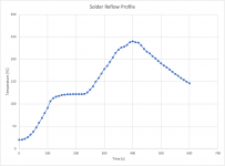
You can see the profile of one of my board runs below. It's pretty close to the recommended profile for Sn/Pb 60/40 solder, though it is longer than the recommended as the toaster oven can't heat up as fast as a real reflow over. I don't use any fancy controls. I just monitor the temperature on a thermometer (Amprobe/Fluke TMD-50) and unplug/replug the oven at strategic points and open the oven door for the cool-down.
Theoretically one would have to be careful when using FR4-PCBs. Glass temperatures of FR4 can be as low as <=130°.
Yeah. I always specify TG130 or better.
Tom
Attachments
Last edited:
Love the toaster oven idea! I had no idea there was any such thing as solder paste and stencils.
A typical workflow for professional/machine assembly is:
- Bake parts if necessary. Clean PCBs.
- Deposit solder paste (screen printed usually).
- Place parts with pick-n-place machine. Hand-place parts that are not machine-placable.
- Solder reflow.
- Place leaded parts (often done by hand -> expensive!)
- Wave solder leaded parts.
- Place and hand-solder any parts that can't handle reflow or wave soldering.
- Clean the flux off the board (unless you're aiming for the lowest cost possible where you'd use no-clean flux to be able to skip this step).
- Inspect and package boards.
The assembly house I use are set up for high-end assembly. By that I mean IPC-A-610 Class 3, which is the same standard used for mission critical and life-supporting electronics. They add several automated optical inspections along the way to ensure that the end product will pass Class 3.
You can read more about it here: The North American Advantage – Neurochrome
Tom
Yeah. I always specify TG130 or better.
You forgot to mention one of the most important differentiating factors of Oshpark
Unlike other PCB-Pooling services, Oshpark mostly uses FR-4 laminates with higher Tg that are more suitable for lead-free reflow and rework. You can get these laminates at some other pooling services as well, but usually only for a significantly higher price. Which is why Oshpark is one of my favourites. Got the recommendation from you a while ago and I am highly satisfied with their services.
Last edited:
- Home
- Amplifiers
- Chip Amps
- Dual-Purpose Multichannel / Stereo Amplifier using Neurochrome Modules