Some reading for you: https://www.edn.com/properly-ground-your-circuits/
This series describes your exact scenario: https://www.edn.com/successful-pcb-...gnal-chips-part-1-principles-of-current-flow/
Follow the recommendations in the article series above and then join the digital and analog grounds at the power supply. There should be no other connections between the digital and analog ground.
That said, the grounding of a volume control chip doesn't have to be super critical. The only time the digital bus is active is when you change the volume setting.
Tom
Last edited:
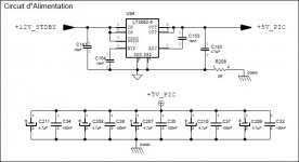
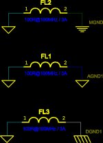
Classic method is to have 2 different ground and you can use a R of 0 ohm or better a self to wiring both. On the PCB, you have a plan for analog GND and a plan for digital GND (on same layer or different layer). Please Find one of my SCM for PGA2320 as example: Power supply GND and analog ground are the same (My power supply is filtered by BNX026H01 so ground is clean), I have a ground for µC PIC and so PGA2320 control circuit and I have a 0 ohms between the 2 ground. On another design I used the following self : LAIRD-HI1206N101R-10.
This design is in operation since many years")
This design is in operation since many years
Attachments
the PGA2311 must have the digital ground connected to the analog ground, what is the best way to connect it using a single toroidal transformer?
Hello
I assume you're trying to prevent the I²C data and clock from getting into the audio. The PGA chips
specify a maximum of 6.25 MHz on the clock. I doubt the PIC can hit that but if so, is there a way to
slow it down? The LT1694 bus accelerator may make thing worse by squaring up the edges. If the
PGA is the only destination you can leave it out.
I'm using 3 cascaded (for control) PGA2311s in my little preamp and drive the SCK and SDI from
digital outputs of an Arduino. I only send data when required and have never heard any digital dirt
in the analog audio. Remember the clock rate does not have to be a steady rate, just the right
number of them so software "bit banging" works fine.
I have the PGAs, opamps and NJW119 tone controls on a 4 layer board with one ground plane and
all grounds tied to that plane. The Arduino is connected via a 10 inch 10 conductor umbilical. The
Arduino +5 power is the same as the signal +5 so I seem to be breaking all the rules but with no
side effects.
G²
The PGA chips
specify a maximum of 6.25 MHz on the clock. I doubt the PIC can hit that but if so, is there a way to
slow it down?
Any microcontroller I've worked with, including ARM most recently, have allowed for setting up the clock source and clock frequency for the I2C peripheral. Want it to go slow? Just set the clock divider to a larger value.
Tom
I assume you're trying to prevent the I²C data and clock from getting into the audio. The PGA chips
specify a maximum of 6.25 MHz on the clock. I doubt the PIC can hit that but if so, is there a way to
slow it down? The LT1694 bus accelerator may make thing worse by squaring up the edges. If the
PGA is the only destination you can leave it out.
I'm using 3 cascaded (for control) PGA2311s in my little preamp and drive the SCK and SDI from
digital outputs of an Arduino. I only send data when required and have never heard any digital dirt
in the analog audio. Remember the clock rate does not have to be a steady rate, just the right
number of them so software "bit banging" works fine.
I have the PGAs, opamps and NJW119 tone controls on a 4 layer board with one ground plane and
all grounds tied to that plane. The Arduino is connected via a 10 inch 10 conductor umbilical. The
Arduino +5 power is the same as the signal +5 so I seem to be breaking all the rules but with no
side effects.
G²
You're absolutely right. Accelerator is not needed if you have only 1 or 2 peripherals on the bus and a short distance. It is even worst in some cases because edges of clock signal are shorter so more EMI.
You don't have my whole schematics but I have a lot of peripherals
For the speed, to control volume or preamp, it's right that you don't need a high speed.
My SCM is just for GND management example. You'r right, it is not mandatory but when you design a big board you don't know in advance if there will have pb so it is in case of.
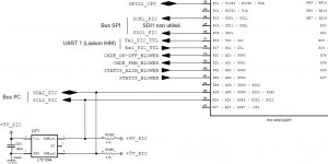
The I²C clock is provided by the µC so speed is configured by the µC and you can choose the speed you want but I think it is only 100kHz or 400kHZ as I²C specification (sure for the PIC I use, don't know for others µC).
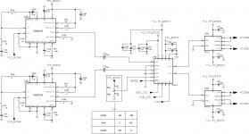
Note that in my SCM, I use the SPI bus to drive a PGA2320 (2311 uses I²C bus). I use the I²C bus for some MAX7312 (I/O expander), TPAXXX (headphone amp), some others stuffs (for external power supply outside the PCB, ...).
The SPI bus could reach a speed of 10Mbps -> it becomes a high speed and so in this case, have separate GND should be done (for example to add an ETH link for your product as remote management. With the PIC you can add a SPI-ETH controler and have a 10Base-T ETH interface. In this case yous should have a GND for analog and a GND for Digital/ETH).
To finish, for fun, I have a riddle: why you ear the lightning in a radio receiver? (help : above topic about short edge of a square wave could help).
- Status
- This old topic is closed. If you want to reopen this topic, contact a moderator using the "Report Post" button.
- Home
- Amplifiers
- Chip Amps
- PGA 2311 gnd