The LG 55UM7000PLC internal speakers are chip amp powered from the board, and my question is if this is a traditional amp - speaker setup, or if it is something else.
My reason for asking is that the TV lacks variable line out, or any analog audio output for that matter and I wanted to get a couple of rear surround channels out of it.
The way I want to accomplish this is by connecting the +left and +right from the internal speakers to the primary side of a 15kOhm 1:1 line transformer after having taken down the speaker level to line level using one 10kOhm resistor on each speaker level feed.
On the secondary side of the line transformer I choose one lead as ground and the other as signal and connect these to an external amp to get the rear surround, these will then only put out the difference between the two front channels.
The problem is that all I get is noise in the rear surround channel, so I suspect there is something going on with the internal amps output to the internal speakers, of which I get my line transformer inputs as described above.
Any ideas or thoughts on why this might be?
Please don't suggest getting an external surround receiver, this is a diy forum after all")
My reason for asking is that the TV lacks variable line out, or any analog audio output for that matter and I wanted to get a couple of rear surround channels out of it.
The way I want to accomplish this is by connecting the +left and +right from the internal speakers to the primary side of a 15kOhm 1:1 line transformer after having taken down the speaker level to line level using one 10kOhm resistor on each speaker level feed.
On the secondary side of the line transformer I choose one lead as ground and the other as signal and connect these to an external amp to get the rear surround, these will then only put out the difference between the two front channels.
The problem is that all I get is noise in the rear surround channel, so I suspect there is something going on with the internal amps output to the internal speakers, of which I get my line transformer inputs as described above.
Any ideas or thoughts on why this might be?
Please don't suggest getting an external surround receiver, this is a diy forum after all
I took the output out directly from the speaker, putting a mono earphone jack, so I could use an external speaker when needed, it was an old colour set with a picture tube.
Now I feed an external amp from a tap off from the set top box that feeds my LCD TV, it has three coax cables, one for picture and two for sound.
The sound cables are tapped, the TV needs a sound signal or it loses the picture (go figure!), and they feed the amp which drives my stereo speakers...no front and back, just left and right.
Volume is set to zero on the TV, I use the set top box and amplifier volume controls to set the level I need.
Or take the signal from the input of the chip amp and feed a small amplifier, 3-10 watts per channel is enough for most use.
Unless your transformers are good, they won't work at audio frequencies with a metal core, you need Ferrite cores.
Just drive the amps through a preset, setting it to about 250 mV output. No transformers.
Or use the TV volume control to set output level.
I would prefer to leave the TV alone and use the audio signal from the set top box if it is available.
Have fun.
Last edited:
Thanks for the thoughts and suggestions, but obtaining a line level stereo output is not the issue, I think that could be arranged, but there is something a bit puzzling to me concerning how the internal amplifiers work since I can't seem to get the +right and +left internal speaker feed to cancel each other out on the primary side of the line transformer.
I have done this before with a more conventional class AB hifi amp without issues, but in this case all I seem to get out on the secondary is noise, instead of the difference between the front right and left channels which is normally what should happen.
The circuit i have between the speaker +right and speaker +left shows roughly 20,15kOhm dcr, that is the two 10kOhm resistors two get down to line level and the dcr of the line transformer primary winding, this should be perfectly safe.
What is different with how internal onboard chip amps for the tv's internal speakers work, assuming they are "class d" chips with a very specific task, compared to normal analogue class AB amplifiers when it comes to things like common ground and similar?
Perhaps, because the TV has no headphone socket the audio is mono. An interesting way to get rear surround though, I'm thinking of trying to get a surround effect from a single enclosure by adding out of phase, rear facing tweeters, I might use a ground loop transformer ( about £3 ) to achieve the signal.
TV lacks variable line out, or any analog audio output for that matter
No SCART ?
If only HDMI with ARC out You can use a cheap converter.
Conversor AV HDMI / RCA
since I can't seem to get the +right and +left internal speaker feed to cancel each other out
Probably the amp chip works in BTL bridge mode.
With the TV off, measure if there is continuity (near 0 Ohm) with one of the wires & ground.
Probably the amp chip works in BTL bridge mode.
With the TV off, measure if there is continuity (near 0 Ohm) with one of the wires & ground.
This was my suspicion, is this common for this type of application? Also would this mean that there is no common ground? That the output is "floating" as in not symmetrical balanced between the channels?, I don't have the possibility to meassure just now, but a common analogue amplifier also usually exhibits a very low output impedance, could be hard to tell.
If I get the possibility I will try to see what chips are powering the speakers, if these are easily identified and not baked into something else.
This is a stereo TV but it has no scart, and would converting the ARC as suggested being me a variable analogue out, my suspicion is that it would be fixed, as would my rear channels in that case.
Things sure where simpler in the old days when variable analogue outputs and conventional amp apologies rained supreme
is this common for this type of application? Also would this mean that there is no common ground?
Pretty standard these days with tiny chip based amps.
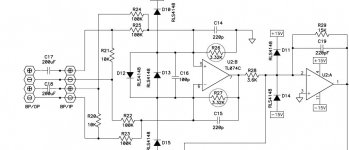
Check this input schematic from my JBL sub.
Note there is no common ground.
ARC as suggested being me a variable analogue out my suspicion is that it would be fixed
Yes ARC is fixed. So you need some sort of converter.
But You could use an All-in-one remote for both TV & DAC.
Attachments
Thanks for explaining, and for proposing alternative solutions.
This bugs me a bit, because it would have been so simple, no extra remotes or devices save for a ultracompact s.m.s.l amp (or similar) under the sofa and two small 2" fullrange speakers, no switching between modes or inputs, everything mixed in stereo would have given a higher experience and everything controlled by the TV remote.
It bugs me that the traditional analouge variable outputs are getting rare, it could even had been a headphone output, but no, very strange and very frustrating, especially when I cannot even use the internal speaker signal to get it.
Sorry for ranting about this, maybe I'm just getting old
Hi Martinsson,
I believe I encountered a similar problem like you. I was disappointed my tv didn't come with RCA outs that were volume controlled by the remote. I soldered my own RCA outs to the internal tv speaker terminals and mounted the jacks to the tv case, I used a low gain amplifier with a volume pot on it, set the volume to 1 to 3 on the remote, set the volume on the amp low and turned it on. It worked, but there was a hum. It took me a while on audio sites to figure out the amp and the tv shared the same ground. I lifted the ground ( might be a dangerous thing to do ) and the hum went away. I now can control the tv with the remote and get great sound. I should incorporate a Felix on the A/C lines then put the ground back.
I like your approach better, makes more sense to reduce the signal to line level first.
I belive there might also be a fair bit of dsp applied as well, even if the signal you use is analouge there is a good chance there is some wiered phase manipulation applied to increase stereo width and add a sense of surround effects, this will all make my approach suffer.
How would using more galvanic isolation, say two more transformers for ground separation help in this case if the mono content (which is to be cancelled out) is still not sharing a common zero so to say, honest question, and if it will do the trick I can see if I can get a couple more transformers.
Using a 10kOhm resistor to atentuate the signal down to line level is a cheap trick, but it works for a given and fairly common power range, say 2 to 20 Volts or so since it effectivly means a 20dB gain reduction, or there about.
1:1 transformers with an impedance between 10-20kOhm with these two 10kOhm resistors in series would mean a total of approximately 20,2kOhm of resistance, 200Ohm from the transformer winding, which should be safe to connector almost any old how in parallel with the amplifier output terminals, at least on a conventional non BTL amp, the question is if the same goes for these type of chip amps, what do you think?
A transformer is an inductive load, you may find that you lose a lot of treble ( as I did when using a single resistor to attenuate the signal ), I'd start of with a 100 ohm with another 50 ohm in parallel with the transformer. I guess the transformer itself will time delay caused by the phase shift, something that I've tried to find more about, but to no avail, a rare time that google has let me down.
The internal amplifier can operate in class D (pulse) with a bridge circuit (no ground). There is no difference signal You need 2 transformers - one from each speaker. The speaker is involved in filtering impulses.
Your interfaces: wireless interfaces: Wi-Fi 802.11ac wired interfaces: HDMI 2.0 x 3, USB x 2, Ethernet, optical audio output
You need 2 transformers - one from each speaker. The speaker is involved in filtering impulses.Your interfaces: wireless interfaces: Wi-Fi 802.11ac wired interfaces: HDMI 2.0 x 3, USB x 2, Ethernet, optical audio output
Last edited:
The transformers are taken from an aftermarket automotive line level ground isolated for those who adds things on to an existing system.or builds their own from scratch, it is rated to have good full bandwidth performance.
Thank you all and especially OldDIY for explaining why all I get with this solution is noise, to bad, for us DIY'ers this is a cheap and easy way to get a bit more out of 2ch content, sadly though this solution is incompatible with these types of amplifiers it seems.
I will not be "forced" to spend more money on a consumer solution due to the inherit technical limitations of the TV, then I'd rather stay with the 2ch presentation as provided by the same.
That tv, and a lot of them today, use an audio output chip that drives the internal speakers - which DOES NOT have a common ground as in older traditional sets.
So..... DO NOT assume or connects both speaker outputs together in any way!
You will fry the chip.
My Panasonic uses that technology, but I got around it by using a 1mFd mylar cap on both the + and the - ends of each speaker to a set of RCA jacks to feed a subwoofer.
To feed my stereo, I use the Optical jack provided, and bought an adapter/converter that converts optical to RCA.
- Home
- Amplifiers
- Chip Amps
- Amp outputs for LG 55um7000 (TV) internal speakers