So..... DO NOT assume or connects both speaker outputs together in any way!
You will fry the chip.
Thank you for this warning, I was not aware that these chips where that sensitive and wrongly assumed a 20,2kOhm load could be tolerated in parallel with the internal speaker load (idealized to 6Ohms in this case) by the amplifiers without risk, but that all seems to be academical at the moment seeing as there is no point in attempting to apply my solution as the signal difference I am after cannot be singled out.
The question comes to mind if the same would have been true for a TV, say a model or two up the chain, using the same amp chips but equipped with line level analogue outputs? My guess is yes but I'm not sure.
The strange thing is, speaker level ground does not come into the picture in my solution, I only use positives of right and left, so even in a BTL scenario, how can this generate noise, it sounds like white noise, how could any signal content of that nature be fed to a speaker?
I normally deal with four figer outputpower labgruppen amplifiers that have plenty of protection features for both inputs and load, so these types of amplifiers is a bit different and less known to me.
So the speakers are not fed a normal analogue signal? Surely it must? Is this a kind of "high power dac" type of chip? Even so the analogue signal (assumption) that reaches the speakers should preferably not carry any content other than what is needed to move the coil right?
I'm just trying to figure out what I'm hearing, the white noise that was the difference between the right and left channel positives, that signal would be part of what was fed to the speakers, so how come it is not audible through the built in speakers?
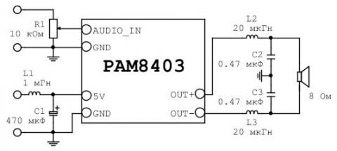
Analog devices. Its microcircuits use a sigma-delta modulator instead of a PWM modulator. This allows the internal frequency to be raised to such a value (2 MHz) that an external low-pass filter is not required. Its functions are performed by a speaker. The internal circuit of such a microcircuit is shown in Figure 5.
The audio signal is obtained by filtering the current through the speaker's voice coil. No audio frequency voltage with respect to ground.
You have a pulse modulated MW band transmitter.
The audio signal is obtained by filtering the current through the speaker's voice coil. No audio frequency voltage with respect to ground.
You have a pulse modulated MW band transmitter.
Last edited:
A similar device will help you ")
https://aliexpress.ru/item/32968955...earchweb0_0,searchweb201602_,searchweb201603_
https://aliexpress.ru/item/32968955...earchweb0_0,searchweb201602_,searchweb201603_
A similar device will help you
https://aliexpress.ru/item/32968955...earchweb0_0,searchweb201602_,searchweb201603_
That's basically what I use to feed audio to my stereo, except it's a Radio Shack version of a toslink/optical input-to RCA audio output.
Thank you for taking the time to explain, that's an efficient and rather clever approach, and it may also explain why there are no additional pure analogue outputs.
The "poor man's fake surround diy solution" I'm inclined to deploy requires a conventional pure analogue output with common ground, speaker or line level does not matter since that can easily be adapted, using any old school solid state amplifier or similar line level device will work just fine.
Just my luck not having any such device to tap from in this case, I can deploy it successfully in other systems around the house and will do so, I think it's a rather clever way to extract a much as possible from 2ch source material all while leaving the original 2ch content unaffected, simply turn of your rear channel amp and there you go.
You can try a bridge balanced circuit (let's call it that))). Like the Letter H. In parallel to each speaker, connect a chain of two 100 ohm resistors. Connect the transformer to the center connection points of the resistors. As the crossbar of the letter H. Place the transformer next to the TV. You can introduce asymmetry into the resistor values or use a 100 ohm pot with 10 ohm fixed resistors on the sides.
Thanks for the suggestion, would this be to first introduce a galavic separation of ground for both speakers, meaning left + and - connected on the primary and take the same out on the secondary, for both right and left speaker channels, then adding resistance in series on both after that? Just a thought, but wont any 100kOhm resistance in series with signal attentuate the signal to much? Seeing as 10kOhm is usually sufficient to get speaker level down to line level.
- Home
- Amplifiers
- Chip Amps
- Amp outputs for LG 55um7000 (TV) internal speakers