Just to give an update, I ran various simulations and made measurements on the amp whilst turning it on and off. As a quick experiment I actually reduced the bias filter capacitor from 100uF to 22uF as per the datasheet. This didn't affect the switch on thump but it did reduce the turn off thump a lot. As I've now made the turn off thump quite small I'm definitely leaning towards installing a relay to handle the turn on thump.
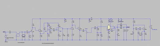
Something else I may try first though is changing the feedback resistors and capacitor. The single supply circuit in the datasheet has these has 10 times the split supply values and the capacitance halved. Running a simulation on this gives the attached results. It doesn't seem to affect the thump (According to simulation) but it seems to make the output settle at a slower rate. I'm wondering why they would want this in comparison to the split supply circuit.
Something else I may try first though is changing the feedback resistors and capacitor. The single supply circuit in the datasheet has these has 10 times the split supply values and the capacitance halved. Running a simulation on this gives the attached results. It doesn't seem to affect the thump (According to simulation) but it seems to make the output settle at a slower rate. I'm wondering why they would want this in comparison to the split supply circuit.
Attachments
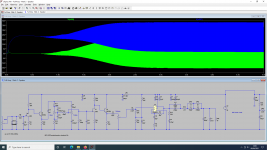
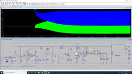
Added to which, I'm wondering if the turn on thump in simulation is correct. According to simulation results, changing the 100uF bias capacitor to 22uF should have increased the turn on thump to 6V! However from real life tests it doesn't appear to have changed it, only reduced turn off thump.
Update: I changed the feedback resistors from 18K/1K to 180K/10K and the capacitor from 22uF to 10uF. The result is the turn off thump has completely disappeared. The turn on thump is now accompanied by a slight buzz for a second, which I belive is normal while the capacitors charge up. I think it's made the turn on thump less severe as well.
As the turn off thump has now disappeared I'm going to look at options for installing a speaker relay. I only need it to be effective for switch on so it shouldn't be too difficult to implement.
As the turn off thump has now disappeared I'm going to look at options for installing a speaker relay. I only need it to be effective for switch on so it shouldn't be too difficult to implement.
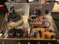
Just to give you all an update, I’ve solved the speaker thump issue. I buiit a small speaker relay board and put a 1K 3W resistor across the output of the PA board. The relay connects the speaker 4-5 seconds after switch on, by which time the thump is reduced to a small pop. I could of gotten rid of it completely but I figured the small pop was useful for telling me the amp was on and operational!
Other mods I did are installing an insulated speaker socket and connecting the speaker ground directly to the filter cap grounds. Did some testing tonight and measured 43W Peak power into an 8Ohm load, which is 32W RMS I believe. I left the amp running at this level for nearly 10minutes and it only just got warm. So pretty pleased! Just need to solve the treble control oscillation now. I’m going to be replacing the tone control wiring with shielded cable and mounting some of the tone components directly onto the pots.
Other mods I did are installing an insulated speaker socket and connecting the speaker ground directly to the filter cap grounds. Did some testing tonight and measured 43W Peak power into an 8Ohm load, which is 32W RMS I believe. I left the amp running at this level for nearly 10minutes and it only just got warm. So pretty pleased! Just need to solve the treble control oscillation now. I’m going to be replacing the tone control wiring with shielded cable and mounting some of the tone components directly onto the pots.
Attachments
....the speaker thump issue. I buiit a small speaker relay board and put a 1K 3W resistor....
You can probably go 100 Ohms without strain on the amplifier.
For super-fast power-up you can use a low-value bleeder and cut it out after some time.
Attachments
Yeah I might rewire it that way. I was torn, the 1K is in parallel to the speaker all the time just in case it gets turned on without a speaker plugged in. Because of this I had to go with 1K so it didn’t get too hot. If I wire it the other way then there’s nothing in place if a speaker isn’t plugged in. For now I think I’ll leave it as it’s working. The next amp though.....
I’ve been trying to resolve this oscillation issue but I’m getting nowhere. I know it’s in the preamp, but I can’t work out what’s causing it. Here’s what I’ve found and tried:
I'm really at a loss. Any ideas would be greatly appreciated.
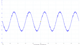
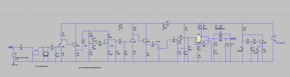
I've attached the latest schematic and what waveform I'm seeing on the 4.7uF capacitor when it's oscillating.
- It occurs in the preamp if I turn the gain and treble up to 10. If I turn the volume up to 10 it occurs in the PA as well.
- I can stop it by turning either the gain, volume or treble down to 8.
- It seems to begin on the preamp output, right at the 4.7uf capacitor. I don’t see it before the second J202 stage.
- I tried putting my signal generator onto the 1uF capacitor and temporarily removing Q2 and it still occurs. So that rules out the first two stages. However if I put the signal generator between the 100pF cap and treble pot it doesn't oscillate.
I'm really at a loss. Any ideas would be greatly appreciated.
I've attached the latest schematic and what waveform I'm seeing on the 4.7uF capacitor when it's oscillating.
Attachments
Hi,
Data sheet of TDA2030 says that minimum gain for stability is 30dB. Currently, your TDA2030 gain is (1+180/10) = 19 which is 25dB. Could you try R6=5k (plug a 10k in parallel on existing R6).
If issue is in preamp, try 100nF ceramic caps with short leads on collectors of Q2 and Q1 to ground. Emitter follower sometimes tend to oscillate.
Chris
Attachments
Yes, for a silly reason. The gain of the preamp was much higher in reality than in simulation and I was struggling to bring the gain down whilst also biasing the transistors correctly. So instead I lowered the voltage to the preamp so I could bias the transistors correctly and have the correct amount of gain. Crude I know, but at the time I couldn't think of another way to do it. In hindsight maybe I should have used negative feedback instead.
Apologies for the TDA2030 model, I'm actually using a LM1875. I've tried finding a model for the LM1875 but can't find anything that works reliably in LTSpice. The PA seems to be stable anyway, it only seems to go mad when the preamp starts oscillating.
I didn't try ceramic caps to ground from the collectors so I'll give that a go. I just tried them to ground on the gate of the J202. Thanks for that.
So I've been reading up on Emitter Follower oscillation and there are a few possible fixes.
- Add a base resistor. Something in the region of 200Ohms.
- Add a resistor in series with the output. 100Ohms should do.
- Power Supply decoupling.
I tried a 100nF on the Emitter Follower's collector to ground, no difference.
I don't think an output resistor will help, I removed all the output wiring and just added a 10K resistor on the other side of the 4.7uF cap to ground and the oscillation remained.
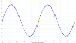
I did more scoping tonight and found that the oscillation does in fact appear a real tiny bit on the input to the second JFET stage and I can reduce it a bit by adding a 100pf to ground from the input. So I'm not even sure if it's the Emitter causing it anymore. I've attached a clearer image of what I'm seeing on the preamp output when it's occurring.
- Add a base resistor. Something in the region of 200Ohms.
- Add a resistor in series with the output. 100Ohms should do.
- Power Supply decoupling.
I tried a 100nF on the Emitter Follower's collector to ground, no difference.
I don't think an output resistor will help, I removed all the output wiring and just added a 10K resistor on the other side of the 4.7uF cap to ground and the oscillation remained.
I did more scoping tonight and found that the oscillation does in fact appear a real tiny bit on the input to the second JFET stage and I can reduce it a bit by adding a 100pf to ground from the input. So I'm not even sure if it's the Emitter causing it anymore. I've attached a clearer image of what I'm seeing on the preamp output when it's occurring.
Attachments
Also I did read an article which mentioned the impedance of the power rail and if anything the high impedance should apparently help. It suggested that if you couldn't add Base Resistance then add it to the power rail. So I'm leaving that as is for now, but I do want to add a zener and reduce R8 as suggested.
Or am I actually seeing two issues here? Is this just noise I'm seeing in this image? Could the issue actually be with my power amp? I have tested the power amp though by putting the scope on the volume pot and hitting it with signals from 1Khz all the way up to 100Khz.
Last edited:
Update:
I've partly sorted the oscillation by doing the following:
- Adding a 47K resistor before the 47pF shunt capacitor in the preamp.
- Adding a 250pF shunt capacitor in the power amp with a 1K resistor in series before it.
The amp still oscillates, but nowhere near as bad. I can now turn all controls on 10 without the amp going crazy. I can still see some oscillation on the edges of the waveform but at least it's not making the amp go insane.
Next time I place an order I'm going to get a 24V Zener to sort out the preamp power rail and when I go to install that I'll take another look at the oscillation issue. The oscillation/noise seems to be all under 100Khz.
Attachments
- Status
- This old topic is closed. If you want to reopen this topic, contact a moderator using the "Report Post" button.
- Home
- Amplifiers
- Chip Amps
- TDA2050/LM1875 Project - Oscillation issues