Fixed, turned the cap around and there's no longer DC on the pot and the DC offset on the output is how it should be.
Remaining items are the oscillation when all controls are full on and the speaker pop on switch on and switch off. I'll trace the oscillation with my scope later to see what's going on there. With regards to the speaker pop it's not instant, it's a second after flicking the switch on. I read a post from J M Fahey where he suggested adding a switch for the speaker output so the speaker can be switched off when turning the amp on. What are people's thoughts on that?
Remaining items are the oscillation when all controls are full on and the speaker pop on switch on and switch off. I'll trace the oscillation with my scope later to see what's going on there. With regards to the speaker pop it's not instant, it's a second after flicking the switch on. I read a post from J M Fahey where he suggested adding a switch for the speaker output so the speaker can be switched off when turning the amp on. What are people's thoughts on that?
")
A first step, without modifying the circuit, would be to increase the time-constant of C11 and associated resistors, to make it significantly larger than that of the feedback network.
If you cannot or don't want to modify the resistor values, increasing C11 is the simplest option.
You would need at least 470µ, probably more to have some useful effect.
Try it in sim first.
This will help with PA problems, but the preamp probably generates its own thumps.
Try the mod with the volume set to zero, to focus on PA issues.
After that, it will be time to examine the upstream circuits, if required
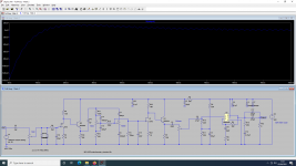
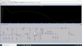
I've simulated a few scenarios and found the following. I did a 100ms simulation measured at the speaker output (Crudely simulated by an 8Ohm resistor in this case). I think the issue is the output capacitor charging up through the speaker and you see in the simulation that the voltage actually momentarily rises above 0 before settling around 0.
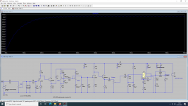
In one simulation I tried to increase R11, R13 and C11 as suggested, but it didn't have any effect on the output. The only difference I could see was that R11 and R13 have nearly 1mA across them when they're 22K and rising to 100K lowers this to 0.2mA.
I then looked at the LM1875 datasheet and noticed that their suggested circuit for single supply has the feedback resistors multiplied by 10 compared with split supply.I tried this in my circuit and the result was the output doesn't seem to spike on switch on. I wonder if that's part of the problem.
The other solution of course is to have a 470Ohm resistor across the speaker output but have a switch to take the speaker out of the circuit for switch on and switch off. Crude, but it would solve the issue. I've read quite a few threads on the issue and it appears most people just seem to live with it.
Attachments
nirupambhowmick I don't actually have a power switch yet, I'm still waiting for it to arrive! At the moment I've just got the power cable hard wired to the transformer primary and am using the wall socket switch. I will bear that in mind for when the switch arrives though.
I think the issue is the output capacitor charging up through the speaker and you see in the simulation that the voltage actually momentarily rises above 0 before settling around 0.
this is just a few nanovolts - should not be audible.
i guess you have to simulate switching on the power supply to see what this does. if you just have a constant DC power supply the simulation does not include switching it on.
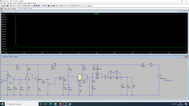
Thank you for the power supply pointer, I can now see the spike!
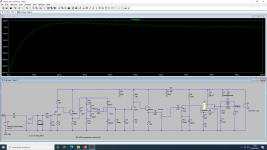
So just by changing the R11 and R13 resistors the spike is reduced by over half. The only downside I can see with this is it means the amp won't be fully operational until at least 10 seconds have passed. Not a big issue. I'll do some more testing.
As for the feedback resistors, they seem to reduce the spike a tiny bit but more than anything they seem to make the output take longer to stabilise.
Attachments
I don't think you simulated the startup conditions properly.
The simplest way to do it is probably to tick the "start supplies at 0V" box.
Your sim directive should look like this: ".tran 100m startup".
Note that a soft thump of a few hundreds mV is not going to be very noticeable.
When it reaches several volts, you have an issue. You should first try to get an amplitude that large on the unmodified circuit sim, and start improvements from there.
Also note that a slowish start is not going to mute the amplifier: it will become operational very quickly, but at first it will clip at lower power than when operating normally, which shouldn't be too much of an issue, except if you have the habit of leaving the volume always at 100%
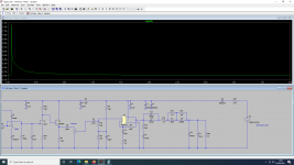
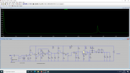
Tested again, this time just with setting the 'start external dc at 0v' setting and the thump is appearing as a 2V spike. Again, increasing the resistors or capacitor you mentioned seems to delay the spike slightly and make it smaller. I also ran a test to see when the amplifier starts to output signal and it doesn't affect this, it starts to amplify at the same time either way.
Are these changes simply making the output capacitors and C11 charge at a slower rate? Thus reducing the thump?
Are these changes simply making the output capacitors and C11 charge at a slower rate? Thus reducing the thump?
Attachments

Apologies for the delayed response, I've been thinking over my options. I think a speaker relay board is still on the cards as I could mount it on the back of the amp. I'm still considering the option you've suggested, however does increasing the bias resistors not affect the DC Offset?
In an AC-coupled amplifier, there is no possible offset shift per-se.
The worst that could happen is a bias shift, which could translate in a slightly asymetric clipping limit.
If this is a concern, you can increase the cap value instead.
That said, my message is certainly not that the time-constants adjustment is a cure-all solution: it is an alley worth exploring, because the costs/mods are minimal, but it cannot totally mute all startup artefacts, unless you are very lucky.
The sure-fire total mute solution is the output relay.
You have to decide whether the residuals are acceptable or not
Ah that makes sense. I would prefer the speaker relay, my only issue at this point is the power for it. In my case I can’t ideally run any AC to it as it would be running past the preamp, so I would need to run it directly off the DC supply, which means it will probably not be effective for switch off transients, only switch on. However the switch off transients aren’t that bad anyway, so that’s not a huge issue.
The final option is a simple switch to disconnect the speaker. Crude, but it’s only myself using this amp so not a huge issue.
The final option is a simple switch to disconnect the speaker. Crude, but it’s only myself using this amp so not a huge issue.
- Status
- This old topic is closed. If you want to reopen this topic, contact a moderator using the "Report Post" button.
- Home
- Amplifiers
- Chip Amps
- TDA2050/LM1875 Project - Oscillation issues