Hello folks,
There are gazzilions of chipamp queries, adding some more. I recently built a chipamp and they sound good. I also took Pano's wonderful Speaker voltage tests. (LINK)
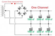
in my small room and I got 1V at speaker terminals for normal listening level. 2 to 3 V at maximum volume level. Nothing else to do and fooling around I measured current draw at Transformer secondary wire. Shown in Red Dots in attached picture. Results were.
At 1v on speaker Terminal = 66mA current
At 2v on speaker Terminal = 100mA current
At 3v on speaker Terminal = 140mA current
At 4v on speaker Terminal = 184mA current
So I will presume that even at 4 times the the volume level I listen I get around roughly 200mA. For Centertapped Dual +/-Ve supply I will presume current draw is aound 0.5A.
my questions are...
1) How low amperage rectifing diodes I can use safely ? Pease give few names.
2) The amp has separate PS Boards and transformers for each channel. I have few capacitors of 1000uf, 2200 uf and 4700uf and of suffecient voltages lying around. Will that be ok if used as shown in the picture ? I suppose having lower or higher value capacitance near amp board doesn't matter. Or Do they ?
3) My transformer wires (length of about 6 inches) coming out of secondary winding coil seems thin. If I cut them close to secondary winding and replace them with thick wires. Would that be of having any advantage ?
4) with Safety and probable future scenario in mind and given my current draw. What value fuses should I use and where ? My transformer is 18-0-18v. Basically I want fuses to blow if amp is driven hard or some mishap occures.
Thanks and regards.
There are gazzilions of chipamp queries, adding some more. I recently built a chipamp and they sound good. I also took Pano's wonderful Speaker voltage tests. (LINK)
in my small room and I got 1V at speaker terminals for normal listening level. 2 to 3 V at maximum volume level. Nothing else to do and fooling around I measured current draw at Transformer secondary wire. Shown in Red Dots in attached picture. Results were.
At 1v on speaker Terminal = 66mA current
At 2v on speaker Terminal = 100mA current
At 3v on speaker Terminal = 140mA current
At 4v on speaker Terminal = 184mA current
So I will presume that even at 4 times the the volume level I listen I get around roughly 200mA. For Centertapped Dual +/-Ve supply I will presume current draw is aound 0.5A.
my questions are...
1) How low amperage rectifing diodes I can use safely ? Pease give few names.
2) The amp has separate PS Boards and transformers for each channel. I have few capacitors of 1000uf, 2200 uf and 4700uf and of suffecient voltages lying around. Will that be ok if used as shown in the picture ? I suppose having lower or higher value capacitance near amp board doesn't matter. Or Do they ?
3) My transformer wires (length of about 6 inches) coming out of secondary winding coil seems thin. If I cut them close to secondary winding and replace them with thick wires. Would that be of having any advantage ?
4) with Safety and probable future scenario in mind and given my current draw. What value fuses should I use and where ? My transformer is 18-0-18v. Basically I want fuses to blow if amp is driven hard or some mishap occures.
Thanks and regards.
Attachments
Hiten, what meter are you using? You can get quite different results with different meters, specially if you buy local. Ideally you want a Trms meter, or capture on a PC and compare it to a signal of known voltage.
Anyway
1) I am happy using SR5100 with a pair of 3886 amplifiers, or the MUR860 without heatsink (similar current capacity). In some cases I've used UF4007, but only with low supply voltages where I know I won't be pushing the amps too hard. Lower current diodes will sag at higher currents, which is a bigger consideration than the absolute If. Generic monolithic bridges are also great for this sort of application, they're far more compact and easy to wire up.
2) Your proposed capacitance layout will work, but better if reversed. Normally we put the cap with the highest ripple rating closest to the rectifier, that would be the largest capacitance assuming all the voltage ratings are the same.
3) Nope. No advantage at all. Use the length that reaches the your PCB and trim off the excess.
4) You don't want to fuse the LM3886 at all. It has sufficient protection built in and in an extreme case should be cheap to replace. It also acts very funny when it loses one rail and since you can't predict the failure mode, it's not worth the risk. You do want a DC offset protection on your speakers, though, as well as adequate and safe slo-blo fusing on the primary (I use 2x VA rating to compute the fuse value for toroids and 1.5x for EI types).
Thanks very much Sangram. You guessed it right Multimeter and ampboards are cheap. But MM does give ballpark figures I hope.
1) Will visit shop and see which diodes available. Currently Using 6A4
2) Capacitors are 1000uf (100V), 2200uf (50V), 4700uf (35V) also have 3300uf (80v). Would like to use them so they dont feel lonely in my drawer.At my home max mains voltage gives me 28V after rectification. Would 35V rated caps be ok ? looking from transformer side can I arrange 4700/35v+2200/50v+1000/100v. OR would 100v 100uf capacitors being high voltage present comparatively high impedance ?
3) Will measure DC at output.
4) My EI transformer are said to be 5A. But conservatively I think 4A guessing mfrs. always cut corners. kindly give fuse values.
5) Efforts are just to get hands dirty and learn as I have bought another good layout PCB and will be buying genuine IC.
Regards.
Isn't that a bit too generous?(I use 2x VA rating to compute the fuse value for toroids and 1.5x for EI types).
Report Post
A slow blow fuse can sustain 150% of it's rated current for an hour.
So for a 230VA transformer you'd use a 2A fuse.(230v input assumed)
150% current is 3A, input power for an hour would be almost 700VA. The transformer will either be very hot or melting already if exactly 3A would flow.
Dibya,
the capacitors on either side of dual supply will be of similar capacitance and voltages. Just wanted to use components that were lying around for this test build. This way I dont waste components and probably increased capacitance will be somewhat usefull.
thanks and regards.
the capacitors on either side of dual supply will be of similar capacitance and voltages. Just wanted to use components that were lying around for this test build. This way I dont waste components and probably increased capacitance will be somewhat usefull.
thanks and regards.
Isn't that a bit too generous?
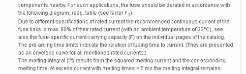
Maybe it is and maybe not. The little thumbnail is something I took from a page at Littelfuse.
Fuses are specified at 23C operating temperature. At typical case and ambient conditions of DIY amplifiers we are looking at a 15-25% derating anyway. Then there's operating voltage, which is never a steady 230V in most parts of our country. Winter nights I've measured 260V off the sockets, which is already above fuse rating.
Then there's the materials used. DIY'ers in India don't have access to properly made fuses, they aren't built to the same spec as a Bussman. They will blow a little short of 2A (in your example). Not ideal but that's what it is. Even with the 'generous' margins, most locally procured fuses will blow on hot start, and need replacing every few months.
For faults on primary side (such as a shorted turn) the fuse will blow immediately. For secondary side faults disconnecting the load effectively removes the load from transformer.
Fuse sizing is always a compromise between self heating, fault protection, surge currents at turn on, and avoiding nuisance blowing. A lot depends on circuit behaviour at turn-on. If we could exactly predict and control startup current and fuse ambient temperature and assure it a steady working voltage, yes, it would be easier.
Attachments
maximum mains voltage I have measured is 245V. And to test because I am newbie I have used 1.5A fuse. Will modify fuses and caps soon.
Also want to know will 35V rated capacitor be ok for my power supply (At maximum mains voltage I will probably get 28-0-28v after rectification) ?
thanks everyone.
Also want to know will 35V rated capacitor be ok for my power supply (At maximum mains voltage I will probably get 28-0-28v after rectification) ?
thanks everyone.
Last edited:
Hiten, the fuse is calculated on actual VA rating of the transformer. It looks like you're trying to use 40VCT transformer at 5A rated maximum current. That would be 200VA, and 1.5A is fine for that transformer. As your secondary capacitance increases, the stress on the fuse will increase so a soft start will be required for larg-ish cap banks. As it is a 1.5A fuse working at 50C ambient is to be derated to just about 1A, which is spot on for that transformer.
35V cap over a 27V loaded secondary voltage is a little on the brink. It's fine for testing but you do need to provide a 15% margin for mains fluctuations and load variations (for example, with disconnected load under protection). This brings you up to 32V, which is very close to cap max rating. Probably OK for testing, but I would really use 40 or 50V caps with those voltages.
35V cap over a 27V loaded secondary voltage is a little on the brink. It's fine for testing but you do need to provide a 15% margin for mains fluctuations and load variations (for example, with disconnected load under protection). This brings you up to 32V, which is very close to cap max rating. Probably OK for testing, but I would really use 40 or 50V caps with those voltages.
Thanks Sangram.
Another reason asking about 35V was I thought since these are unbranded caps what if some times amp is overstressed for long durations. That would be same as having a low voltage caps. Isn't it ?
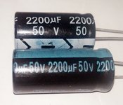
As I wanted some missing caps to make identical pairs for power supply I bought 2200uf 50V. But Old and new one does not match. The new ones are 5mm short in length (Diameter is same) and they weigh as if they are only aluminum cans with nothing inside. So I bought only one. The new one weighted 6.8 g my old ones are 10.7g. Doubtful, I think I will go for higher voltages and capacitances than normally required.
Branded are not available and probably not be worth in my cheap build. sometimes cheap builds are good for learning as I desire to make safe stable amplifier from cheap parts from whats available point of view.
I will be building another chipamp with genuine parts when new PCBs arrive.
Another reason asking about 35V was I thought since these are unbranded caps what if some times amp is overstressed for long durations. That would be same as having a low voltage caps. Isn't it ?
As I wanted some missing caps to make identical pairs for power supply I bought 2200uf 50V. But Old and new one does not match. The new ones are 5mm short in length (Diameter is same) and they weigh as if they are only aluminum cans with nothing inside. So I bought only one. The new one weighted 6.8 g my old ones are 10.7g. Doubtful, I think I will go for higher voltages and capacitances than normally required.
Branded are not available and probably not be worth in my cheap build. sometimes cheap builds are good for learning as I desire to make safe stable amplifier from cheap parts from whats available point of view.
I will be building another chipamp with genuine parts when new PCBs arrive.
Attachments
Last edited:
Voltage tolerance is a tricky thing, and different from self-heating under extreme load.
While the first is usually a hard red line and an absolute max, the second does reduce cap life a little more gradually.
I've had decent luck with properly made capacitors regardless of country of origin and never used/would use components available in the local market unless it's an emergency. They are rated very ambitiously, both in terms of capacity and voltage rating. I've also had parts which had the jacket turned 180 degrees and the leads of the same length. Had to throw out an entire lot of 200 capacitors because of this, and swore off the local market.
OK. Probably will discard the idea of using spare capacitors I already have.
I have new IEC C5 type socket which I intend to use. It also has EMI filter (wires wound over ring). I know lots will depend on how I assemble amps in side enclosure. Strangely I did not have any hum or noise while testing. Modules / Transformers / PS all were out in open and no star ground as such. If I use three wire mains socket I can be sure of Live mains wire goes to power switch and ultimately to transformer lead Primary where Fuse will be present. In short the three wire mains lead will make sure the live wire has fuse.
So my question is will it be good idea to have Earth wire connected to Metal amp chassis instead of leaving it unconnected in chassis ?
It is mandatory to connect the main earth to the chassis, and then to every other exposed metal part that a user can touch.
This is non-negotiable. This also means your RCA sockets have to connect to chassis ground. If you use insulated RCAs then power ground has to connect directly to chassis as well.
If this causes hum due to high resistance of earth wires in power leads and wall, you can use a breaking circuit between chassis and power ground with a resistor, a bridge rectifier and a capacitor. The circuit is outlined in Rod Eliot's pages.
It is not legal to use 2-pin mains wiring with transformers that are not double-insulated. Every transformer made in India for general hobbyist and service personnel use are not, and so the use of three wires is mandatory.
hello Sangram,
sorry for late update kindly bare with me. I had ordered an enclosure with plan to assemble. I did received it but the front and back panel needs heavy modification. and the modification is costing as much as enclosure. will bother you once that is done with layout. meanwhile few thoughts came to my mind.
It is collective wisdom that lm3886 should not be supplied high voltages then recommended with low ohms. Suppose we have 2 way speaker with crossover at 3.5khz. what if we implement two chipamp per channel/speaker where at source we attenauate fq. below (lets say) 2khz for tweeter and above 4khz for woofer. Increase supply to both chipamp so with limited frequency we put easy load on the amps have high voltage supply. ICs see not so complex driver+crossover impedance. Would that be worth it or will have only minimal advantages ?
thanks and regards.
Kain Chho?
Where are you?
Get Keltron capacitors, use 50 or even 63 volts. Buy from reputed dealer as even those are being faked now, and Japanese are available with some dealers.
Some Chinese are decent, but Japanese, European and Keltron are good in audio.
Use 4007 diodes, Schottky are not needed at 50 Hz.
Scrap SMPS will yield plenty of caps and diodes, large caps and fan too.
Usually decent quality unless capacitors bulged.
- Home
- Amplifiers
- Chip Amps
- Few LM3886 Chipamp questions (hopefully differnt)