for start ground I will take EXTRA wire from (1) Speaker terminal pin ground (2) Signal input pin ground (3) Amplifier Module Speaker Out ground (4) Power supply board Rectified 0v Ground to the Center point shown in green circle Which will have Mains Earth wire connected to metal chassis. Tell me if this is correct ?
The main goal is to have one central (star) ground point to avoid ground loops by not having multiple uneven length ground connections. Even if the amplifier works, ground loops degrade the SQ. Ideally you have a center ground (the star) with equally (short) paths. If you've got an amplifier board, that should already be in its design. To add further connections like separate speaker ground or input ground to case points means you'll introduce ground loops. You've got a connection point where the ground connectons are collected but you've got it with a lot different path length far off center. Of course it's often not possible to get an ideal star ground position, your wiring depiction leaves well room for improvements though.
Thanks ICG.
as there was no reply I abandoned the connections scheme shown in the picture and went ahead with rest of the build. My build is compact and symmetrical. I have made star ground with only space available at center of chassis floor and is near power supply boards. As of now I have connected only AC mains Earth and Two separate power supply Board's 0v connection to the same point. Length of leads from PS board 0v to the star ground is 1.5 inches.
I connected source input ground at back panel metal chassis with 1nf ceramic capacitor in series. Signal wire goes directly to volume control. Still have to make power connection etc. as my two pole mains switch broke and had to replace.
Out of curiosity before making wiring for power supply I measured transformer primary windings. One transformer is showing 100 ohms primary resistance, other is showing 440 ohms primary resistance. which is strange as they both are from same company with same specs of 18-0-18v output & 240v input. The whole amplifier was mock tested outside the case and was working perfect.
Any idea why difference in primary resistance ?
Regards
Actually a star ground is not the greatest grounding scheme. The performance depends a lot of where you place the star, but you can do better with a well-designed ground plane. You can read about that in more detail here: Taming the LM3886 Chip Amplifier: Grounding – Neurochrome
Tom
Tom
Sorted out. I re soldered the PS and wiring and tested the amp on test speakers for half an hour. Music is pouring out. There is no hum or turn on thump(Filter caps are 18800uf per channel). IC and heatsink is barely warm (DC supply voltage 24-0-24v). Things look ok.
regards
regards
Hi,
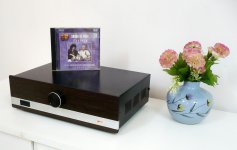
I have finished my amp build here are couple of pictures. This was fun/cheap build during lockdown and I built it when time permitted and when I got hold of proper parts/spares.
More pictures and description Here.
I have run it for almost one hour with no room fan and it hardly gets warm. DC volts I am getting are +/-29v Absolutely no turn On thump etc. I shut down while music is playing and it plays on for about 3 seconds to be safe to discharge caps. There were lots of compulsions, moving goal posts so it is not as I wanted it. In hurry I have put neon power on light (Parallel to mains) as its only purpose is to switch off amp when not in use. please do point out mistakes. Infact would be obliged for any rectification/changes
Regards
Attachments
")
I run one at +/-19V and it measures and sounds great. Only issue is maximum power is reduced, but there's no difference if you're not looking for the maximum. 8ohm is a theoretical average, most speakers do not exhibit anything near that sort of impedance through the range.
I regularly run them at 25V unless in multiples, so that the same amplifier can run different kinds of speakers, and not be stressed when dealing with impedance swings. With such weak output stages, it's better to err on the side of caution.
I regularly run them at 25V unless in multiples, so that the same amplifier can run different kinds of speakers, and not be stressed when dealing with impedance swings. With such weak output stages, it's better to err on the side of caution.
Thanks Nirupam. Mostly for average listening levels I am ok with around 16 watts (Including transients)as calculated HERE. So this LM3886 may have little more margin. However this was my fun/learning/getting hands dirty build and will probably be replaced by another amp.I don't want to ruin your happiness but +/-25vDC (loaded?) is quite low for 8ohm drivers & lm3886.
-------------------------------------------------------------------------------------
I suppose 1.5A fuse are OK ? (They are on primary side of the each transformer) in addition I have put one more common 1.5A fuse where the AC mains wire comes in to the chassis. (This was unavoidable situation because of change in plan)
Regards

Hello everyone,
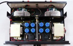
I added Tone control and Phono preamplifier (In separate chassis) to the build. Sharing some pictures.

Inside...

1) Chinese tone control board (2) CNC Phono PS (3) CNC Phono Preamp build from kit by me (4) RF Blocking capacitor
from common ground to chassis ground (5) Insulating sheet between board and metal chassis (6) Magnetic shield
(7) Separate Transformer for Phono preamp
Due to lack of shielded wire I used Signal and ground separate, twisted wire for each input. Mains earth is connected to paint removed metal chassis in center shared along with 0v from Tone and Phono board power supply. So far no hum or any noise.
More details are shared HERE. as I didnt wanted to repeat

Thanks and regards.
I added Tone control and Phono preamplifier (In separate chassis) to the build. Sharing some pictures.
Inside...
1) Chinese tone control board (2) CNC Phono PS (3) CNC Phono Preamp build from kit by me (4) RF Blocking capacitor
from common ground to chassis ground (5) Insulating sheet between board and metal chassis (6) Magnetic shield
(7) Separate Transformer for Phono preamp
Due to lack of shielded wire I used Signal and ground separate, twisted wire for each input. Mains earth is connected to paint removed metal chassis in center shared along with 0v from Tone and Phono board power supply. So far no hum or any noise.
More details are shared HERE. as I didnt wanted to repeat
Thanks and regards.
Last edited:
- Home
- Amplifiers
- Chip Amps
- Few LM3886 Chipamp questions (hopefully differnt)