Bit tired tonight, can't remember what was said in this thread...
Since we lowered the input cutoff frequency, is the low cutoff frequency of the feedback loop still OK - I mean way lower?
Say if C1 is now 4.7uF, is C2 now say higher than 470uF (if I get the schematic right)?
Sorry for the probably stupid question, just looking at the last schematic and making sure the FB is not trying to handle a low frequency it can't...
Have a nice WE
Claude
Claude: the use of the DC Servo circuit automatically voids the use of C2 & C17. If the servo is eliminated you then want the R3+C2 low frequency cutoff at the feedback loop to be at least (say) 5X lower than what is set by C1+R2 (which sets the high pass filter at ~1.7Hz) then a 680uF cap should be called for. Are my calculations correct folks?
A question..what is the function of R20 and how was it calculated?
Cheers, Pete
R20 100k is simply a resistor to help tie the input to some ground to keep the inputs from having too much EMI/RF pickup when an input is left floating and not connected. It’s optional. I added that after I noticed noise when left floating. It’s good practice and 100k is so big as to not really present a real load to any preamp signal. It could be 220k even.
R20 100k is simply a resistor to help tie the input to some ground to keep the inputs from having too much EMI/RF pickup when an input is left floating and not connected. It’s optional. I added that after I noticed noise when left floating. It’s good practice and 100k is so big as to not really present a real load to any preamp signal. It could be 220k even.
Thank you X!
Pete
Hi Pete,
Thanks for your kind reply. Yes of course, in case someone doesn't populate the DC servo (for whatever reason).
I just thought for consistency puposes the schematics could be updated. The lastest I have, and I am glimpsing at it late at night- time permitting - has indeed the mention of the 4.7uF input cap option, but no corresponding option for C2 then, whereas I would have thought C2 then needs mandatory to be amended accordingly... if fitted obviously.
I took yesterday factor 4 and ended up by quick head calculation with 470uF, just to give a rough ball park raising the potential issue in the post.
5x gives indeed the next pratical value of 680uF, you are correct. If not populating the DC servo. However, we are moving to Fc= 0.31Hz for the FB, quite a low value by my standard. No clue if it is an issue or not, with that chip or not, I will leave the experts on that.
But as said, one doesn't need at the input Fc=1.7Hz, that's IMHO very low for nothing. Fc=5Hz will do the job very easily and that means C201= 1.6uF.
Note taht if feeling more comfortable with Fc=4Hz, then would mean 2uF.
Now, if not populating the DC servo (again, not saying one should, but for consistency on the schematics) and taking say factor 4 lower Fc for the FB loop (I believe that's quite enough), then one would end up with C2= 170uF (for input Fc=5Hz), respectively 220uF (a common value) for the 4Hz input Fc. In any case we would have the FB Fc being higher or equal to 1Hz.
With all these options and changes it might be good to issue revised schematics with the right values and possibly the comments on what to populate / what related options there are on the schematics so one hasn't to read the entire thread to find out how to interpretate them?
Perhaps best done once the final values are completely confirmed, as I feel quite a few things are still being fine tuned. That's the beauty of the community "being on it".
Have fun
Claude
Hi Claude, I was just looking for the actual quote from Paul McGowan, of PS Audio fame, where he made the statement about how they get such good bass response in their amps..his response (not verbatim) was that whatever components they set up to give them what’s considered a good low end response (whatever high frequency cutoff filter lower end) they make it even lower than that by 5X, 10, even higher. Similar to the old saying attributed to the upper crust women of society “You can never be too thin or too rich,”. I think you take bass down as low as you can do so w/o compromising cost benefits or sound. Just because one’s speakers only are rated down to 30Hz say, if you add a 15” passive subwoofer later on you want the bottom there to make it worth it. Music always sounds better with a nice bottom response too.
If you use a 1.5uF input cap that would give you about a 5.3Hz cutoff. A 220uF cap at C2 would a give an approx. cutoff of ~1Hz which is about a 5X margin lower. Yes?
What I’m hearing so far is that the 4.7uF MKP4 WIMA (limiting the choice to what’s on our BOM) is the way to go at C1/C101. Beautiful bottom response and signal clarity.
Cheers, Pete


Yeah, well nothing wrong with having some extra margin... if you can afford to or if it doesn't affect other bits of course, lower Fc can't really harm.
I too dont 'like to compromise bass, my LS aren't bass reflex (closed box) and go down to 25Hz -3dB, and then slow slope... and I like classic music.
Having said that, there are so many rules of the thumb in audio, like 10x impedance, 10x Fc... as of me (and that's just me) I like to understand what I am really dealing with and see what can be optimised... or not. That's just me again
Here we have a simple 1st order high pass. Let's see how it works. Fc=5Hz (-3dB)... gives you -0.26dB @ 20Hz. OK, in real life, nothing is perfect, and perhaps it works out to be a tad more (or even less?), but you get the point. In real life, there are far more deviations elsewhere than these, although indeed some could add up. At 35Hz you have -0.09dB... barely measurable probably, and in theory you never get to 0dB of course as it is a never ending quest LOL.
Note Fc=2Hz gives you still -0.04dB @ 20Hz. That's indeed less, won't argue, and even more neglieable.
One shouldn't really consider indeed more than 5Hz for a full range system IMHO, although some litterature will say 7Hz OK etc. In real life, if you haven't got the choice, taking 4Hz is more than enough. Lower Fc works also well, but let's face it: it isn't what gives more bass , as the difference between Fc=2Hz and 4Hz is really negligeable in a listening room, not to mention other components (and ears can't notice these small differences). At that point you are probably rather chosing the capacity manufacturer that suits your bass favours by sound rather than by value, and in that respect some bigger caps may sound different indeed, or even some with higher voltage rating say some... who knows")
All academic and just to share my POV, no real added value and no need to change anything of course: As long as you have what suits you, all is fine!
And all this is ways better than the intial recommandation that could indeed per se only cut off bass response quite a bit!
Take care
Claude
I too dont 'like to compromise bass, my LS aren't bass reflex (closed box) and go down to 25Hz -3dB, and then slow slope... and I like classic music.
Having said that, there are so many rules of the thumb in audio, like 10x impedance, 10x Fc... as of me (and that's just me) I like to understand what I am really dealing with and see what can be optimised... or not. That's just me again
Here we have a simple 1st order high pass. Let's see how it works. Fc=5Hz (-3dB)... gives you -0.26dB @ 20Hz. OK, in real life, nothing is perfect, and perhaps it works out to be a tad more (or even less?), but you get the point. In real life, there are far more deviations elsewhere than these, although indeed some could add up. At 35Hz you have -0.09dB... barely measurable probably, and in theory you never get to 0dB of course as it is a never ending quest LOL.
Note Fc=2Hz gives you still -0.04dB @ 20Hz. That's indeed less, won't argue, and even more neglieable.
One shouldn't really consider indeed more than 5Hz for a full range system IMHO, although some litterature will say 7Hz OK etc. In real life, if you haven't got the choice, taking 4Hz is more than enough. Lower Fc works also well, but let's face it: it isn't what gives more bass , as the difference between Fc=2Hz and 4Hz is really negligeable in a listening room, not to mention other components (and ears can't notice these small differences). At that point you are probably rather chosing the capacity manufacturer that suits your bass favours by sound rather than by value, and in that respect some bigger caps may sound different indeed, or even some with higher voltage rating say some... who knows
All academic and just to share my POV, no real added value and no need to change anything of course: As long as you have what suits you, all is fine!
And all this is ways better than the intial recommandation that could indeed per se only cut off bass response quite a bit!
Take care
Claude
WE nearly over, so just for the fun...
All these being decibels, not a scale easy to apprehend, put in terms of linear voltage losses... the worst case 5Hz cutoff means 97% voltage at 20Hz, so 3% less than message ( loss). Indeed some losses vs 2Hz which is less than 1%.
Now to put that in perspective, -3dB is 30% voltage loss.
Just for the sake of having one extra post here, sorry for the off topic
Claude
My rule of thumb is to set the corner frequency at least 2 octaves below where I want it flat. So flat to 20Hz means 5Hz corner frequency for a -6dB/octave 1st order filter. Some people like to hit subwoofer to 10Hz flat levels so then the corner frequency should be about 2.5Hz. But like the saying that Turion mentioned, one can never be too thin or too rich.
Last edited:
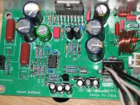
I am testing one board and have consistent -4.5 V at the speaker out put. It has the servo populated and C2 has been replaced with a jumper. First power up was with a variac and the -4.5 was present at +/- 20V . My supply is reading +/_ 37v. The lm317 shows +15.19 volts and the lm337 is -15.19. Pin 7 of the 718 is +15.19 and pin 4 is -15.19. pin 6 read 10.6v.
Any ideas where to look? I will post some images shortly. My only change was to use 22ga wire for the inductor all else is to the jan 13 BOM.
Thank you
Any ideas where to look? I will post some images shortly. My only change was to use 22ga wire for the inductor all else is to the jan 13 BOM.
Thank you
Ok Pulled R15 replaced C2 0.00V offset. And it is playing now. Sounds clean on a little speaker in a cigar box.
Double checked the resistors I used 47.5K for R15 and 332K for R16, R17, R18 and R19. Now i just have to make sure all is in the right place, Everything looks good on the second board. I'll take some images to see if someone can see something I am missing.
Thanks again X
Double checked the resistors I used 47.5K for R15 and 332K for R16, R17, R18 and R19. Now i just have to make sure all is in the right place, Everything looks good on the second board. I'll take some images to see if someone can see something I am missing.
Thanks again X
- Home
- Amplifiers
- Chip Amps
- Xmas Amp - Dibya's TDA7293 by Jhofland