I want to add a driver to the suggested "typical" topology of an amplifier based on the NEC uPA1225h. I have a bunch of modules I pulled from a Sonance power amp that I repurposed the chassis of.
The modules are based on a uPA1225 chip that feeds a single pair of output devices. Basically a common emitter stage. In this configuration it gives about 50w into 8ohm and 75w into 4 ohms per spec. In reality a bit higher. with +/-45vc rails.
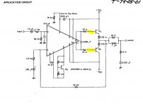
I have attached the typical application/ suggested OP configuration.
I would like to make a small modification to be able to drive a 2 ohm load but keep running off the +/-45vdc rails since I have the transformer for it.
I did add more OP's devices in parallel, but now the limitation is the IC's protection circuit which limits current delivered by the internal drivers.
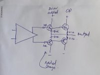
Given that I have a few spares (drivers etc) lying around, I "inserted" an extra stage after the chip and before the OP devices. I checked the amp for stability (phase compensation related disasters) and it seems to be stable.
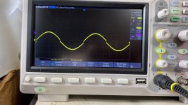
However I have no idea what resistances to use for degeneration etc. The amplifier seems to run fine, however there is what seems to be crossover distortion or something that is present at lower volumes, and goes away with higher signal. (pls see trace), obviously, there is no bias now, I probably need more bias given the extra stage... but not being a trained EE, this is getting beyond me...
can anyone help out with some suggested values for the extra stage.
The modules are based on a uPA1225 chip that feeds a single pair of output devices. Basically a common emitter stage. In this configuration it gives about 50w into 8ohm and 75w into 4 ohms per spec. In reality a bit higher. with +/-45vc rails.
I have attached the typical application/ suggested OP configuration.
I would like to make a small modification to be able to drive a 2 ohm load but keep running off the +/-45vdc rails since I have the transformer for it.
I did add more OP's devices in parallel, but now the limitation is the IC's protection circuit which limits current delivered by the internal drivers.
Given that I have a few spares (drivers etc) lying around, I "inserted" an extra stage after the chip and before the OP devices. I checked the amp for stability (phase compensation related disasters) and it seems to be stable.
However I have no idea what resistances to use for degeneration etc. The amplifier seems to run fine, however there is what seems to be crossover distortion or something that is present at lower volumes, and goes away with higher signal. (pls see trace), obviously, there is no bias now, I probably need more bias given the extra stage... but not being a trained EE, this is getting beyond me...
can anyone help out with some suggested values for the extra stage.
Attachments
- Status
- This old topic is closed. If you want to reopen this topic, contact a moderator using the "Report Post" button.