The second round for power supply
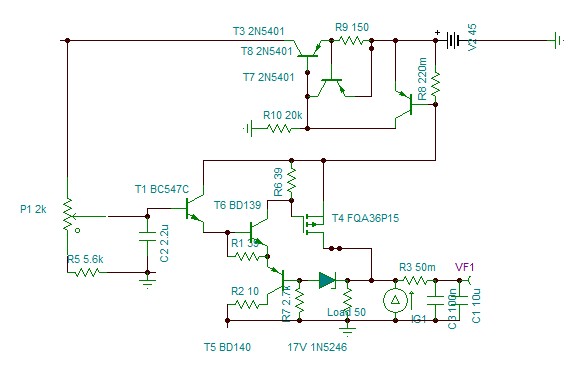
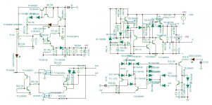
I will provide each channel its own regulator to be installed very near if not on board. The 50m ohm is wiring resistance. It requires only 10uF capacitor, both BDs are mounted on heatsink 1.5w each dissipation. I will add a dc detector by two opto couplers on the amp output, to trigger a scr and protect the speaker.
The output impedance is very uniform resistive.
Attachments
Last edited:
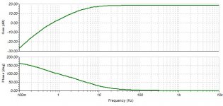
Now adjusted, it flies high to 22Mhz. It needs a minimum 27p grounding the input.

I am dealing with the input coupling capacitor charge plop on start up. I must review all the start up mute.
As it is CFA, it also needs a dc servo.
Distortion estimation gives 0.00055% at mid power.
Attachments
Last edited:
Understanding the distortion estimation.
The CFA opamo now became a WB, wide band, amplifier has initially high open loop distortion. Of course the feedback decreases it but also the higher impedance of the negative input.
This is the internal input stage in principle. The current generated by the difference of the inputs due to internal 100ohm and external negative impedance are harvested at collectors by current mirrors and by internal resistor transforms the differential current into voltage to be followed by unity gain diamond follower. The distortion is mainly due to non linear character of the base-emitters Ic/Vbe. If I apply a very high resistor in series with the 100ohm than the nonlinear character becomes less significant.
With 8K it measures at 1.5V out 0.02% only in open loop. The problem now, the power stage distortion of 0.01% to add, is no more negligible. If I increase the gain of the power from 9.2 to 20 lets say, the distortion becomes 0.02+0.02% but As I doubled the gain and deviding it by 8.5 I have extra NFB of 20/8.5=2.3 times and my total closed loop distortion is (0.02+0.02)/2.3=0.017%÷by the gain of the WB. In other words with gain of 20 I must multiply the measured by simulator distortion by 0.02/0.017=by 1.17. The sumulator is measuring 0.00018% hence my distortion neglecting noise issues is 0.00021%.
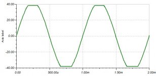
I am trying to limit the saturation. This is the output unlimited.
and this with limiter and a gain of 15.

As shown , already the power alone has bad saturation, with composite it becomes horrible. Also to note that this occurs in PBTL at 100w. My problem with diode limiters distortion becomes 100 times higher. I must find much sharper limiter than diodes.
The CFA opamo now became a WB, wide band, amplifier has initially high open loop distortion. Of course the feedback decreases it but also the higher impedance of the negative input.
This is the internal input stage in principle. The current generated by the difference of the inputs due to internal 100ohm and external negative impedance are harvested at collectors by current mirrors and by internal resistor transforms the differential current into voltage to be followed by unity gain diamond follower. The distortion is mainly due to non linear character of the base-emitters Ic/Vbe. If I apply a very high resistor in series with the 100ohm than the nonlinear character becomes less significant.
With 8K it measures at 1.5V out 0.02% only in open loop. The problem now, the power stage distortion of 0.01% to add, is no more negligible. If I increase the gain of the power from 9.2 to 20 lets say, the distortion becomes 0.02+0.02% but As I doubled the gain and deviding it by 8.5 I have extra NFB of 20/8.5=2.3 times and my total closed loop distortion is (0.02+0.02)/2.3=0.017%÷by the gain of the WB. In other words with gain of 20 I must multiply the measured by simulator distortion by 0.02/0.017=by 1.17. The sumulator is measuring 0.00018% hence my distortion neglecting noise issues is 0.00021%.
I am trying to limit the saturation. This is the output unlimited.
and this with limiter and a gain of 15.
As shown , already the power alone has bad saturation, with composite it becomes horrible. Also to note that this occurs in PBTL at 100w. My problem with diode limiters distortion becomes 100 times higher. I must find much sharper limiter than diodes.
Attachments
Last edited:
clipper
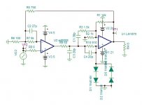
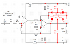
I found better to clip by feedback with zeners. By this any gain adjust is possible and it will clip at required output voltage determined by zeners and a less extent the series resistors. As it feedback it is possible also to provoke soft clipping starting from 80w to clipping.
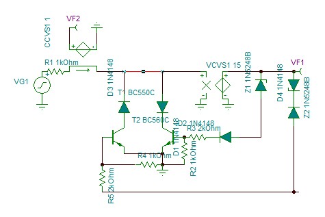
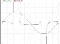
The oscillograph shows the current in 100na scale drawn from the input, just at start of clipping.

I found better to clip by feedback with zeners. By this any gain adjust is possible and it will clip at required output voltage determined by zeners and a less extent the series resistors. As it feedback it is possible also to provoke soft clipping starting from 80w to clipping.
The oscillograph shows the current in 100na scale drawn from the input, just at start of clipping.
Attachments
Final 1st round clipper
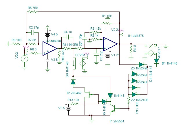
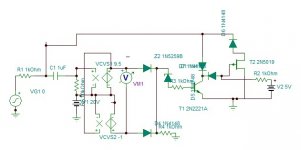
This is the best version I got. It will have four Zener diodes to determine the max power the user wants to limit. It is 90W, 50W,25w ,12W. The choiceof Pjfet is not yet determined.Must precise that it works in revers current.
The graph bellow shows the current the limiter pulling from the composite.

I discovered from vast distortion curves of AD8008 on datasheet, This amp is designed to function at low impedance of 150ohm where it has it lowest distortion. The data is given for Mhz range. On simulator the lowest distortion about 50% lower than high impedance I have at 420 ohm.
This is the best version I got. It will have four Zener diodes to determine the max power the user wants to limit. It is 90W, 50W,25w ,12W. The choiceof Pjfet is not yet determined.Must precise that it works in revers current.
The graph bellow shows the current the limiter pulling from the composite.
I discovered from vast distortion curves of AD8008 on datasheet, This amp is designed to function at low impedance of 150ohm where it has it lowest distortion. The data is given for Mhz range. On simulator the lowest distortion about 50% lower than high impedance I have at 420 ohm.
Attachments
Last edited:
Understanding the distortion estimation.
The CFA opamo now became a WB, wide band, amplifier has initially high open loop distortion. Of course the feedback decreases it but also the higher impedance of the negative input. View attachment 899249
This is the internal input stage in principle. The current generated by the difference of the inputs due to internal 100ohm and external negative impedance are harvested at collectors by current mirrors and by internal resistor transforms the differential current into voltage to be followed by unity gain diamond follower. The distortion is mainly due to non linear character of the base-emitters Ic/Vbe. If I apply a very high resistor in series with the 100ohm than the nonlinear character becomes less significant.
With 8K it measures at 1.5V out 0.02% only in open loop. The problem now, the power stage distortion of 0.01% to add, is no more negligible. If I increase the gain of the power from 9.2 to 20 lets say, the distortion becomes 0.02+0.02% but As I doubled the gain and deviding it by 8.5 I have extra NFB of 20/8.5=2.3 times and my total closed loop distortion is (0.02+0.02)/2.3=0.017%÷by the gain of the WB. In other words with gain of 20 I must multiply the measured by simulator distortion by 0.02/0.017=by 1.17. The sumulator is measuring 0.00018% hence my distortion neglecting noise issues is 0.00021%.
I am trying to limit the saturation. This is the output unlimited. View attachment 899248
and this with limiter and a gain of 15.
View attachment 899247
As shown , already the power alone has bad saturation, with composite it becomes horrible. Also to note that this occurs in PBTL at 100w. My problem with diode limiters distortion becomes 100 times higher. I must find much sharper limiter than diodes.
If you want say 20W into 8R multiply these together and find the square root and multiply that by root 2. That will give the peak positive and negative voltages you need to swing. That gives 17.9V peak or 35.8V peak to peak.
To avoid clipping you need higher voltage on your supply rails to allow for the voltage drops across the power transistors in the LM1875 chip.
This device has internal protection and it seems a better idea to increase the supply rails than having the dilemma of doing this by complex other means.
The clipping problem has been resolved. It needs a Led indicator that triggers for half a second and find a suitable switching Pfet.
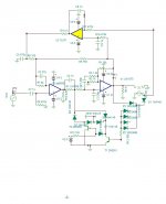
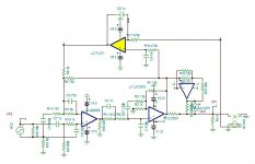
There are two issues that needs to be treated together, The charge of the input capacitor on start up and the DC servo that necessary for CFA. For DC servo I need a differential amplifier plus an integrator, similar to my error corrector. So, why not make it both functions with the same circuit. This is the subject simmering in my thoughts.
There are two issues that needs to be treated together, The charge of the input capacitor on start up and the DC servo that necessary for CFA. For DC servo I need a differential amplifier plus an integrator, similar to my error corrector. So, why not make it both functions with the same circuit. This is the subject simmering in my thoughts.
Last edited:
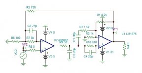
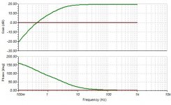
Here is the differential servo installed. I adjusted 5Hz -3db. Despite the input WB has dissymetric inputs dc impedances to provoke offset, the servo brings it to 5uV on the output. By this the input capacitor loading high impedance, high quality non polarized capacitor can be used.
I can now simplify my complicated start/stop plop circuit.
Attachments
The grounding of the feedback 100 ohms has paramount importance. To be independent from the output impedance of the servo, I grounded it by a capacitor. Now the opamp can be the old TL71 with 20uV offset error. The low frequency cut now is second order.
Attachments
Last edited:
I modified the low voltage +/-5 volt regulator and added a delay on start up. With C6 100uF it delays 10 seconds to allow the capacitors charge to V/2. The V/2 on the emitter of T9. The amp starts/stops at 32V supply with no delay on shutdown.

I added resistors in series with the BD transistors to reduce their dissipation to 0.5W. The output impedance is always 0.5 ohms.
Attachments
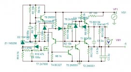
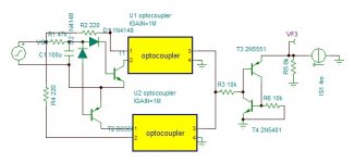
Loudspeaker protection
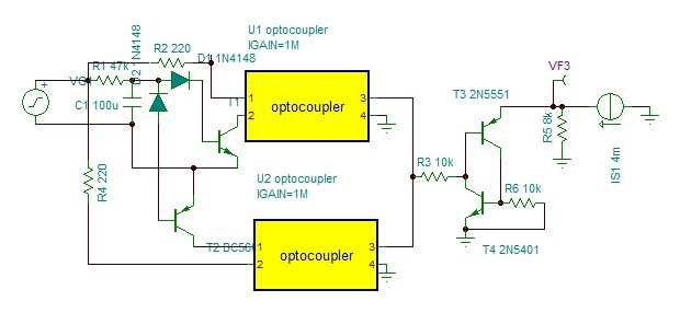
This speaker protection shuts down the power supply if a DC is detected. The 47k/100uF(bi-polar electrolytic) is adjusted so that a square wave of 40vp 5hz doesn't trigger. The minimum trigger DC is 1.2V. If A DC 2V is applied then after 3 seconds it triggers. If 40V is applied, 100ms only.
The optocouplers are PC817, the current source and the resistor are elements from the power supply's reference voltage. To restart, the amplifier should be reseted. I must add a Led to indicate the security shutdown.
Attachments
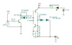
peak indicator
I thought I will find very easily a peak indicator, particularly in tape recorders. The requirement is to have the LED remains on for half a second to show a peak has reached for a duration as low as few micro seconds. Yes I found such function but using several opamps. The most commonly used circuit is this.

In duration is ok but not for very short pulses.
I decided once again design my own way and came up with the following.
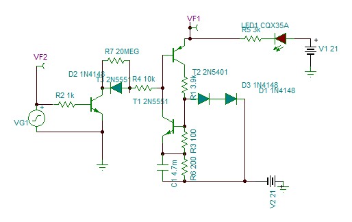
It can trigger for pulses down to 1us, and remain 0.5 seconds. The input transistor is the one in the clipper circuit.
I thought I will find very easily a peak indicator, particularly in tape recorders. The requirement is to have the LED remains on for half a second to show a peak has reached for a duration as low as few micro seconds. Yes I found such function but using several opamps. The most commonly used circuit is this.
In duration is ok but not for very short pulses.
I decided once again design my own way and came up with the following.
It can trigger for pulses down to 1us, and remain 0.5 seconds. The input transistor is the one in the clipper circuit.
Attachments
The opamp current vs frequency not counting the 420 ohms load measured across R9 is.With a parallel feed involving a power amplifier block and a high speed op.amp feeding into a common load ask yourself what of levels of current are passed by each of these and what individual voltages will in the nfb signal if the power amplifier block is able to deliver 4 A and the high speed op.amp around 100 m.a. or less.

As the maximum is 10Mhz with 1v input I get 13ma peak.

I don't have any 100ma current, although the opamp is conceived for capacitive loading of much higher peak currents. What do you mean by "individual voltages will in the NFB signal" ?
With current multiplier my fr. response fell back to 10Mhz but reduced the slight resonance that I had anticipated. By adding 27pF necessary input capacitor and 1k resistor to decouple from source impedance along the ground loop breaking resistor, this gives the result.

Attachments
Last edited:
- Status
- This old topic is closed. If you want to reopen this topic, contact a moderator using the "Report Post" button.
- Home
- Amplifiers
- Chip Amps
- The LM1875 for best