
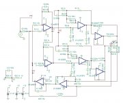
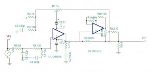
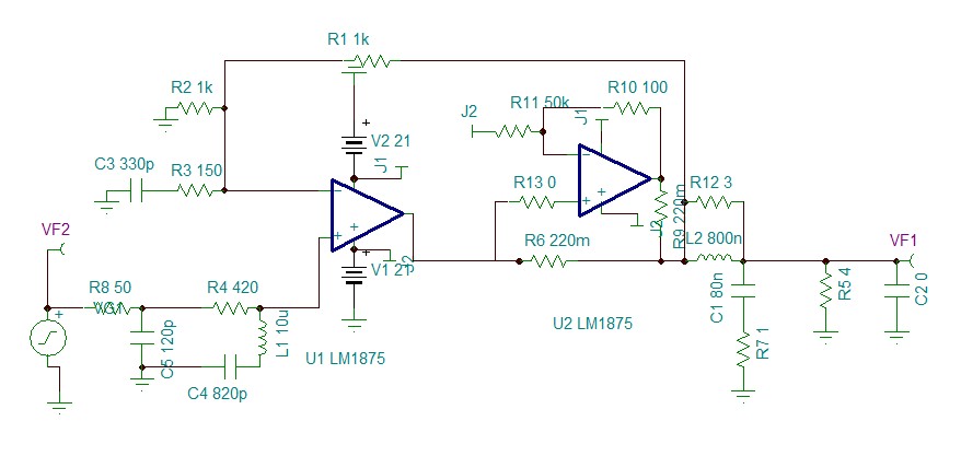
This version uses both sides of the bridge to be adjusted by the error amplifier.
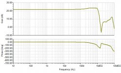
The error amp which can use AD8620 has the following response.

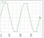
At 1khz it re-injects the error 36 times detected on the output. The transient response remains excellent see 500ns and 20ns scale.


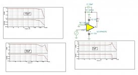
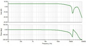
What is great with error amplifier as you can see the bellow frequency response on contrary the composite it doesn't effect the frequency character of the amplifier as the error amp intervenes only on low frequency, 0db at 28khz.
To estimate the distortion: The datasheet LM1875 says 0.02% for a gain 20, hence 0.002% for gain of 2. The AD826 has very low distortion and mainly even orders. the input with the gain of 3 gets its pairs subtracted but not that of unity inverter. If we consider that the LM1875 has also even ones to be subtracted, than a gross-o-modo estimation can be 0.004% on the output. The error amplifier decreases by 36 times at 1khz, this results 0.0002%.
I tried with spice model AD8620, it gives 99% identical result except that the OLG is modeled only 140 V/V instead of V/mv.
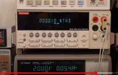
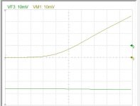
You can see on the scope, the output doesn't have any offset, as the jfet input similar to DC servo adjust by itself the offset. The green curves are the error signals.
Attachments
Last edited:

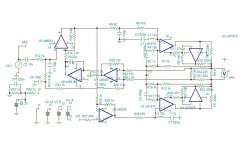
I start to transform into single supply. I replaced the opamps to have low offset.
I chose LM4562 instead of my favorite AD826, to be in conformity with the member's choice, although much slower, it could be adjusted well. The jfets I tried the OPA637, identical to 627 but stable above 5 gain but far more affordable. The error amp can be replaced by adjustment, on the other hand the input with gain of 3, I was expecting oscillation to try to find solution, worked perfectly, even better than the 627.
A bridge amp need two offset adjustments. The Vcc/2 of the outputs and differential offset. Here the power amps bring the Vcc/2 and the error corrector provides the differential offset. I have 15mv on the output left to take care of. The slowness of LM4562 created some transient defect but corrected other, as can be seen on 500ns scale graph.


Last edited:

It looks like the slow opamp is matching better. The reason is the transient start. As the power amp is only 1Mhz, the first 40ns is dominated by it. If I use a faster error differential amp than the slow rising slope of the power breaks, trying to rectify the error to match the input. Now adjusted both offset and speed, the transient is near perfection. 100ns scale.

I found on Youtube a distortion measurement of LM1875, showing 0.01%.
I listened the recordings of LM1875 on Youtube, The best sounding is reduced power to 10W max, but simple music LM1875 10W ? DIATONE DS-600ZX - YouTube
Here you can here how bad it becomes when many instruments burst.DIY LM1875 --- Test1 - YouTube.
Attachments


View attachment 897405
It looks like the slow opamp is matching better. The reason is the transient start. As the power amp is only 1Mhz, the first 40ns is dominated by it. If I use a faster error differential amp than the slow rising slope of the power breaks, trying to rectify the error to match the input. Now adjusted both offset and speed, the transient is near perfection. 100ns scale.
These points were covered in the article linked in post 27 which explained the choice of AD711 as the right partner for LM1875 in a composite amplifier - basically not too fast and not too slow.
In the pdf go to page 37 page 39 in the article and see the last paragraph which continues to page 40.
I watched these measurements, LM1875 IC audio amplifier board kit test and review - YouTube
LM1875 audio amplifier kit ULTIMATE power test - YouTube
I need to higher my gain from 12 to 16, so the input stage will run at gain of 4.
Thank you for the LM2134. I have never seen this circuit employed. LT1057 looks very popular for LTspice designers as it is included model.
The technic of error corrector is much different than composite. In composite, the output must be highest possible pole so that the opamp carries the dominant pole. If you want to give 20db extra NFB, to reduce the gain by 10 times, than the op amp must be 10 times slower. In my case it must run at 100khz only. With error corrector, the error loop being independent from the amplifier's it can have it's own speed at will depending up to what frequency you need to correct.
vzaichenko in no-global-loop-amplification uses AD844.
In theory, I need a ultra fast input and inverter amplifiers so that the amplifier's speed remains that of the outputs. The input than must be delayed as much for comparison and the error should be amplified at very high speed to submit correction. As the error amplifier must have a gain of the amplifier and the correction gain, in my case will be 16×10 you can realize that the error amp must be ultra fast . Now, all these are new to me that I teaching myself. I will tryout today with LM2134.
Last edited:

I went back to the beginning, now that I understood what it should result. I was comparing the output, reduced to input level with directly with the input. I don't have intention to correct its high frequency behavior, so I pass the input through a low pass of same frequency or lower than the amplifier, and ask the amp to imitate it. To reach so, as I had to increase the gain, I increased the input by 10%, instead of decreasing as much on the output feedback, I decreased it 20% so that the error is not working at null but with slight signal so that it resembles the output.

The amp for now has offset problems due to AD826 and the erroneous simulated gain of AD8610. The frequency response is back to original, The initial transient is that of open loop, I am now satisfied.
Attachments
I review the output stage. I delay the input stage to match the inverter by 47ohm/68pF. I reduced the Q of the anti resonator and increased the resonant frequency. The feedback made including the current multiplier without inductance. Although I had 1.4mv offset, I balanced to few uV.
The result is very smooth transient see 20ns,200ns,500ns scale for 10khz 10v start.


The square wave 10khz 10v


where it goes wrong is at saturation when the amp is biased 200ma but ok without.


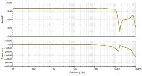
The frequency response. It is possible to eliminate the notch, may be it is security to avoid oscillation that occur at high currents.
Attachments
This is the final of second round. The error signal now follows the output up to 1Mhz instead of 30khz on first trial.

I have now 22p compensation instead of 150p which had about 4 times distortion reduction at 10khz. The Inductor L3 can be eliminatef by adding a capacitor on R34. unfortunatly my simulator stops working even it is 0pF. To say that it takes several minutes to resolve such complicated circuit. I will switch to LTspice may be I get faster resolution.
I will start now the power supply .
Attachments
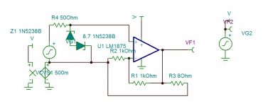
I am testing for clipping and start/stop plops. For saturation, ad my input voltage is high a pair of zener 8.7v diodes on C5, is sufficient to clip just before the amp at 8 ohms load. See at 10khz.

I can see the plop, The problem is that the supply voltages of the opamps +/-12v must be very fast following the 42v main. Not easy but possible.
I can see the plop, The problem is that the supply voltages of the opamps +/-12v must be very fast following the 42v main. Not easy but possible.
Attachments
Last edited:
output network
This is the output Zobel network for each side.
This is square wave 10khz response with only 4 ohms load.

And this, with 100nF along 4 ohms load.

I used the snubber after the LR because this how I understand the function of this network. The other way is to follow thumb rules. Most Japanese brands and McIntosh use this way.
This is the output Zobel network for each side.
This is square wave 10khz response with only 4 ohms load.
And this, with 100nF along 4 ohms load.
I used the snubber after the LR because this how I understand the function of this network. The other way is to follow thumb rules. Most Japanese brands and McIntosh use this way.
Attachments

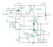
Power supply for opamps

This is regulated supply of 24v always centered in the single supply from34v to 45v. To avoid plop at start up and shutdown the 33v zener conducts at about 34v to conduct the supply switch transistor, a hysteresis resistor R11 provokes frank switching to avoid linearity and parasite.
The output impedances are bellow 0.5 ohm on simulator, but in real world I always got 0.2 ohms with BD139 at 100ma.


+V to -V -----------------------------+V To ground

-V to ground
This is regulated supply of 24v always centered in the single supply from34v to 45v. To avoid plop at start up and shutdown the 33v zener conducts at about 34v to conduct the supply switch transistor, a hysteresis resistor R11 provokes frank switching to avoid linearity and parasite.
The output impedances are bellow 0.5 ohm on simulator, but in real world I always got 0.2 ohms with BD139 at 100ma.
+V to -V -----------------------------+V To ground
-V to ground
Attachments
- Status
- This old topic is closed. If you want to reopen this topic, contact a moderator using the "Report Post" button.
- Home
- Amplifiers
- Chip Amps
- The LM1875 for best