Understanding the LM1875
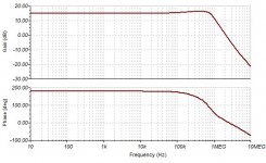
This amp is in fact a power opamp with open loop frequency of 70hz and 90db gain. This is measured with 2k load. If the output is a tranconductance amplifier as I can guess from the internal circuit, than the OLG/BW depend upon the load. This is not specified but what betrays is the need of output snubber to limit the gain for inductive load at high frequencies. If the output impedance vs frequency could inform the distortion vs frequency does also and it is provided.
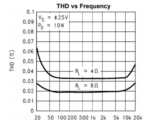
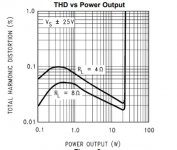
One can see that the distortion is flat to 10khz, this means with 8 ohms load it has the same NFB on the whole spectrum despite decreasing gain shown on OLG curve for 2k load. Comparatively see that of LM3886.

If you look at low frequency distortion of LM1875 you can see it start rising bellow 70hz as the compensation capacitor is no more providing the internal feedback. If you look that of LM3886, although the OLBW is few hertz it starts distorting bellow 200hz Why?. This phenomena occurs in IC amplifiers because the temperature variations of the outputs alter the Hfe of the low power transistors provoking nonlinearities. The LM1875 not only better conceived but also the measurement is done at a point where the power dissipation remains constant, hence less internal temperature variations.

If look at 4 ohms load curve distortion starts at higher frequency and gets double at 20hz vs 1.5. This is due to variable power dissipation at measured point
conclusion, This amp can give it's best when it is running at constant temperature/dissipation. The curve for best sound is that of 8 ohms load with +/-20v supply with maximum power at 1% distortion of 17w.
This amp is in fact a power opamp with open loop frequency of 70hz and 90db gain. This is measured with 2k load. If the output is a tranconductance amplifier as I can guess from the internal circuit, than the OLG/BW depend upon the load. This is not specified but what betrays is the need of output snubber to limit the gain for inductive load at high frequencies. If the output impedance vs frequency could inform the distortion vs frequency does also and it is provided.
One can see that the distortion is flat to 10khz, this means with 8 ohms load it has the same NFB on the whole spectrum despite decreasing gain shown on OLG curve for 2k load. Comparatively see that of LM3886.
If you look at low frequency distortion of LM1875 you can see it start rising bellow 70hz as the compensation capacitor is no more providing the internal feedback. If you look that of LM3886, although the OLBW is few hertz it starts distorting bellow 200hz Why?. This phenomena occurs in IC amplifiers because the temperature variations of the outputs alter the Hfe of the low power transistors provoking nonlinearities. The LM1875 not only better conceived but also the measurement is done at a point where the power dissipation remains constant, hence less internal temperature variations.
If look at 4 ohms load curve distortion starts at higher frequency and gets double at 20hz vs 1.5. This is due to variable power dissipation at measured point
conclusion, This amp can give it's best when it is running at constant temperature/dissipation. The curve for best sound is that of 8 ohms load with +/-20v supply with maximum power at 1% distortion of 17w.
Attachments
My experience with the chip is that it is quite a bit better sounding than the 3886 (in spite of "worse" paper spec), but implementation is key. It is not as stable/reliable/indestructible as the 3886, conversely its simplicity makes it easier to get good sound.
However one must stay clear of the temptation to minimise the component count. It needs control over the turn-off thump, lacking any form of low Vs-muting. It also needs substantial number of components in the input side to ensure stability and good distortion performance. You've already covered the Zobel, this is pretty much mandatory for these chips.
I like to use it as a tweeter/mid amplifier in active systems. The current limit is a little on the low side for proper full range performance into medium sensitivity speakers. I am also keen to see how it behaves with current feedback, for more demanding loads. I have a few of these built out that run on 21V rails, and they sound superb. There is an output relay that drops out before the chip, so turn-off thump is avoided.
Keen to see where you go with this.
Chris, I'm using LM3886 for LF duty running off the same supply. While the output power into the same load is the same, it runs more relaxed during higher current passages.
I find the 3886 more neutral but the 1875 has a nicer quality in the midrange. I can't put a quantity to it though I would like to, at some point. A well-implemented 3886 can sound superb.
Mooly, that is quite the doodle It's an interesting approach, but the chips are only used to provide DC balance, correct? I used this sort of an approach to bridge TDA2030s together in the early part o the century, and repeated the 'trick' to bridge LM3886s for a subwoofer application (8 ohm driver).
I find the 3886 more neutral but the 1875 has a nicer quality in the midrange. I can't put a quantity to it though I would like to, at some point. A well-implemented 3886 can sound superb.
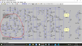
Mooly, that is quite the doodle
It's an interesting approach, but the chips are only used to provide DC balance, correct? I used this sort of an approach to bridge TDA2030s together in the early part o the century, and repeated the 'trick' to bridge LM3886s for a subwoofer application (8 ohm driver).Thanks
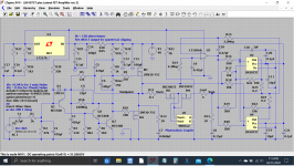
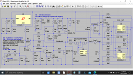
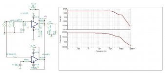
It is a true bridged design. The lat fet front end is one half and the parallel chips are the other half configured as inverting voltage followers.
Nothing says bridged amps have to use identical stages
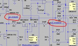
The chips run with increased noise gain for stability in the unity gain configuration which is provided by R19 and R20.
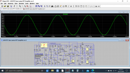
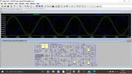
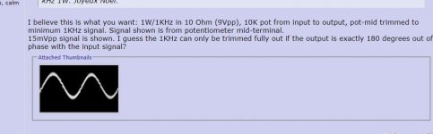
This shows the voltage output of the front end stage and the chip amp stage with its 180 degree phase shift.
The small opamp (a servo) provides active biasing of the chip stage to maintain a perfect zero volts DC offset across the load.
A FET speaker relay and photovoltaic coupler which would be driven from extra circuitry to provide a switch on/off mute function.
It is a true bridged design. The lat fet front end is one half and the parallel chips are the other half configured as inverting voltage followers.
Nothing says bridged amps have to use identical stages
The chips run with increased noise gain for stability in the unity gain configuration which is provided by R19 and R20.
This shows the voltage output of the front end stage and the chip amp stage with its 180 degree phase shift.
The small opamp (a servo) provides active biasing of the chip stage to maintain a perfect zero volts DC offset across the load.
A FET speaker relay and photovoltaic coupler which would be driven from extra circuitry to provide a switch on/off mute function.
Attachments
I decided to design the LM1875 for its best. First I will study the character in detail , sort out the problems to resolve and bring solutions to get highest quality possible. It can be paralleled and bridged, it can be composite or not.
Hayk
How about nested?
Attachments
Mooly, the problem with this approach is that the drive of the inverting section is taken from the "dirty" end of the non-inverting section. I usually reserve this configuration for bass duty (using chips at both ends, FWIW). A transformer would probably be a cheaper way to achieve similar results with 3x 1875s at either end, and it might even sound a bit better.
I'm not worried about unequal halves because you'll get a little less harmonic cancellation, which is not always a terrible thing.
I'm not worried about unequal halves because you'll get a little less harmonic cancellation, which is not always a terrible thing.
Its kind of deliberate is that, honest... because the lateral front ends sound so good, they have a unique sort of character and so using that output to feed the other half goes a way to preserving that without adding 'pure chip amp' sound to the mix.
Its all experimental and doodling at the moment
Maybe it would be something to play with though and I have a very good phase splitter from a Diamond Buffer bridge amp.
Its all experimental and doodling at the moment
Maybe it would be something to play with though and I have a very good phase splitter from a Diamond Buffer bridge amp.
Attachments
Troubles with LM1875
The problems need to resolve I see, are the following.
The crossover distortion.
The lack of power, only 16 good watts.
Bellow 2W, lack of dissipation.
Distortion 0.02%, too high for nowadays.
The pins are not enough thick.
Start/sleep noise suppression.
The crossover distortion exhibits at 0.5w for 8 ohms load.


As one can see from 4 ohms load, 0.7 times the max of 8 ohms, the problem is the bias current.
Lack of power.
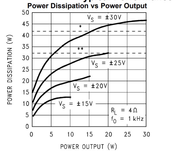
This circuit is optimized for 16w only. The casing mounted directly on heatsink has 3°C/W T. resistance. It has a drop out of 4V on each rail. Paralleling two units is must for 4 ohms load to have a decent 30w, or bridged paralleled for 8ohm 60w.
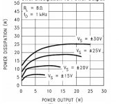
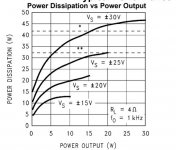
lack of dissipation bellow 2w.

To keep constant die temperature, the dissipation falls bellow 2w at +/-20v. This can cause low frequency distortion adding further to the crossover. The graph stops at 14w. This curve is for 8 ohms but bassreflex speakers fall to 6.2 ohms minimum, running it at 21v it will result higher dissipation.
Distortion 0.02%.
This is for a gain of 20 (26db). It can be 20 times lower if it is running with unity gain, if further 20db extra NFB applied by the composite, 0.0002% is at reach.
The pins.
The leads are equivalent of 0.68mm thick wire. The American Wire Gauge table shows max 1A power transmission. This is RMS 1A. If two units are paralleled, 2A can be used. This results a maximum 32w for 8 ohm.
Start/sleep noise.
A quality amplifier cannot start or sleep by farthing. This issue depends upon the power supply type single or split, bridged or not bridged.
The problems need to resolve I see, are the following.
The crossover distortion.
The lack of power, only 16 good watts.
Bellow 2W, lack of dissipation.
Distortion 0.02%, too high for nowadays.
The pins are not enough thick.
Start/sleep noise suppression.
The crossover distortion exhibits at 0.5w for 8 ohms load.
As one can see from 4 ohms load, 0.7 times the max of 8 ohms, the problem is the bias current.
Lack of power.
This circuit is optimized for 16w only. The casing mounted directly on heatsink has 3°C/W T. resistance. It has a drop out of 4V on each rail. Paralleling two units is must for 4 ohms load to have a decent 30w, or bridged paralleled for 8ohm 60w.
lack of dissipation bellow 2w.
To keep constant die temperature, the dissipation falls bellow 2w at +/-20v. This can cause low frequency distortion adding further to the crossover. The graph stops at 14w. This curve is for 8 ohms but bassreflex speakers fall to 6.2 ohms minimum, running it at 21v it will result higher dissipation.
Distortion 0.02%.
This is for a gain of 20 (26db). It can be 20 times lower if it is running with unity gain, if further 20db extra NFB applied by the composite, 0.0002% is at reach.
The pins.
The leads are equivalent of 0.68mm thick wire. The American Wire Gauge table shows max 1A power transmission. This is RMS 1A. If two units are paralleled, 2A can be used. This results a maximum 32w for 8 ohm.
Start/sleep noise.
A quality amplifier cannot start or sleep by farthing. This issue depends upon the power supply type single or split, bridged or not bridged.
Attachments

Thanks for the start/stop issues. If people arrived at 21v rail, no doubt it is adjusted by ears, adopted.My experience with the chip is that it is quite a bit better sounding than the 3886 (in spite of "worse" paper spec), but implementation is key. It is not as stable/reliable/indestructible as the 3886, conversely its simplicity makes it easier to get good sound.
However one must stay clear of the temptation to minimise the component count. It needs control over the turn-off thump, lacking any form of low Vs-muting. It also needs substantial number of components in the input side to ensure stability and good distortion performance. You've already covered the Zobel, this is pretty much mandatory for these chips.
I like to use it as a tweeter/mid amplifier in active systems. The current limit is a little on the low side for proper full range performance into medium sensitivity speakers. I am also keen to see how it behaves with current feedback, for more demanding loads. I have a few of these built out that run on 21V rails, and they sound superb. There is an output relay that drops out before the chip, so turn-off thump is avoided.
Keen to see where you go with this.
This music Happy Together - The Turtles (1967) - YouTube cannot be reproduced by LM3886 with 26db gain, the chorus refrain goes dirty. Can you please try out comparatively with LM1875. If you love too much the 3886 you can consolate yourself blaming the MP3, as normally people do.
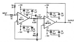
People call this composite. This circuit doesn't work, FauxFrench tried it out.How about nested?
"My_Fef"2
ANDREA a Democratic hybrid amp for luxury sound
These are my best composites power amps. I posted to others several other examples.
ANDREA a Democratic hybrid amp for luxury sound
These are my best composites power amps. I posted to others several other examples.
Resolving the problems
The crossover distortion can be lowered if I bias at higher current. This can be done if the paralleled amp is of current nature, so a dc offset current can make each amp function in class A at low power. How much offset current ? The offset current will make the two amps dissipate more, as it is required to increase the low level dissipation, the dissipation vs output power curve will decide.
The amp may look like this.
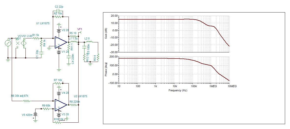
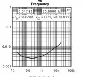
The current amp is an open loop feeding the load with half the current that it needs, the voltage amp measures the error and provides the other halve up to a certain frequency determined by the output LR inductor. Above this frequency the amplifier becomes a current amplifier increasing its voltage by increasing the load impedance. Example, if the load is a full range with 100uH VC inductance L2, you see the bellow graph the amplitude rises. This principle have great chance to yield smooth very high definition tweeter sound .
Propositions, critics ant comments, are welcomed.
Hayk
The crossover distortion can be lowered if I bias at higher current. This can be done if the paralleled amp is of current nature, so a dc offset current can make each amp function in class A at low power. How much offset current ? The offset current will make the two amps dissipate more, as it is required to increase the low level dissipation, the dissipation vs output power curve will decide.
The amp may look like this.
The current amp is an open loop feeding the load with half the current that it needs, the voltage amp measures the error and provides the other halve up to a certain frequency determined by the output LR inductor. Above this frequency the amplifier becomes a current amplifier increasing its voltage by increasing the load impedance. Example, if the load is a full range with 100uH VC inductance L2, you see the bellow graph the amplitude rises. This principle have great chance to yield smooth very high definition tweeter sound .
Propositions, critics ant comments, are welcomed.
Hayk
Attachments
Last edited:
- Status
- This old topic is closed. If you want to reopen this topic, contact a moderator using the "Report Post" button.
- Home
- Amplifiers
- Chip Amps
- The LM1875 for best