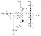
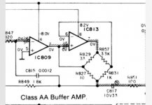
This is derived from class aa buffer of Technics, see bellow.
The left amp is the master, the slave tries to decrease the master's current to null as power steering. by un balancing the bridge with 200 instead of 100 ohms the slave provides only halve of the output current.
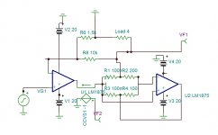
In this version two slave power amps are under the command of an opamp.
It requires precise adjustment to get the opamp steer the output with very little current. This amp can have less than 0.0003% distortion.
Attachments
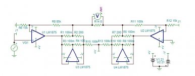
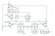
I will start with this model as it doesn't need fine adjustments to function correctly. The central 100k resistors bias the amps 210ma, to be adjusted for linear dissipation. It can deliver 70 good watts, but with distortion of about 0.02%.
To correct the non linearity, I will not use composite but Hawksford error corrector. Mine, shown bellow called the Reactor, Is different type but works on the same principle. I need to adapt for differential feedback, and will act only on one side of the bridge .
Attachments
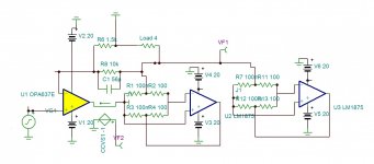
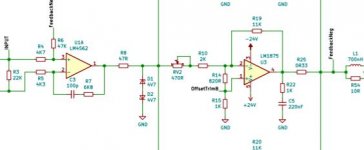
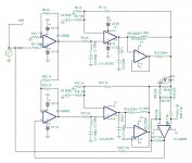
This is a different way of bridge. The right hand side is a unity inverter. The error circuit when adjusted to required gain by R26 goes to minimum and adds or subtracts the distortion or phase as shown bellow. The error opamp needs to be jfet as it functions also as dc servo. I used here OPA627 but AD8610/20 can replace. The AD8008, the ultra low distortion/noise 450Mhz CFD opamp is far superior, can be used only with single supply.
As I see this thread doesn't attract much interest.
Hayk
Attachments
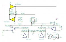
This is a different way of bridge. The right hand side is a unity inverter. The error circuit when adjusted to required gain by R26 goes to minimum and adds or subtracts the distortion or phase as shown bellow. The error opamp needs to be jfet as it functions also as dc servo. I used here OPA627 but AD8610/20 can replace. The AD8008, the ultra low distortion/noise 450Mhz CFD opamp is far superior, can be used only with single supply.
As I see this thread doesn't attract much interest.
Hayk
You have posted so many variations of a theme it is hard to know if these are simulations or circuits where you have done some breadboard testing.
While the LM1875 is relatively cheap the other op.amps are not, which is probably enough to put people off.
This device has a minimum closed loop gain of 10 which is for an 8R impedance. What level of driven impedances are you looking at that would change that situation.
The composite amplifier mentioned by adason that you dismissed was authored by a group that included Scott Wurcer who is responsible for some high spec IC designs.
Here is a link https://worldradiohistory.com/Archive-Radio-Electronics/90s/1992/Radio-Electronics-1992-11.pdf from page 36 onwards.
Hi Mjona. I am glade that you give interest for this subject. I am continuing what FauxFrench has started on LM1875 in parallel configuration and used in a composite amplifier..
FF and chermann did lot of tests and measurments that I am relying upon, I proposed also several solutions and composites. For now I am away from home and I don't think I'll be back soon, so all these circuits are research to get uncompromised best from LM1875 and it is far to be reached. For now, thanks to this project, I created two new circuits, the Hec differential and floating interactive current amplifier. There are still lot of problems to resolve, here is an example.
I asked Sangram on post 16 to listen a music comparatively to LM3886 which can qualify to my standard as entry level HIFI. It remained a dead silence response, so I presume that it is at least as bad if not worst. To continue, I need first to resolve the open loop phase shift problem.
PS: AD8610 costs 1$ from Ali.
Last edited:
Sangram might have discovered as I did that LM1875 modules can cut in and out at higher power levels. I ran these singles from +/- 22 Volt regulated supplies I had on hand for my JLH existing 1996 power amplifier - which did not misbehave in this way.
I had some correspondence with Sakura Systems' proprietor in 1999 but did not ask him which chip he was using. The thought had been that the chip modules might be as good as the Class A and not run so hot and consume so much power.
I believe one high end manufacturer has made composite power amplifiers from parallel LM modules whether 3875 or 3886.
I have acquired a few commercial amplifiers in my time. One of these is a Technics Class
AA design - model SU-VX720. I have a service manual for this.


This is the defect of LM1875 transient response sin 10khz , left, with gain of -10 scale 20ns. You can see that it has 40ns blindness. The ideal is on the right for 160khz low pass RC. This blindness behaves as crossover distortion, the output not seeing the input. It occurs only on the start of a burst, as the phase reaches the output -90° OL and needs to bring by feedback to that of CL. If the OL phase is less, or the delay is lower, than the blindness time decreases.
Last edited:
Sorry, been looking at the thread but haven't found time to contribute.
I do have both 3886 and 1875 on hand. Both have issues at high power levels. I can't actually reach those levels though, not anymore at least. The last speaker that I found to excite this issue was the Dynaudio BM6, which I no longer own. The 3886 would cut out at moderate power levels, and two in parallel were needed.
To add a bit of confusion, I have not had two modules set up in the exact same way with the same gain, source and load for a meaningful comparison. However I have done a quick listening session last week. At lower gain the 3886 catches up with the 1875 quite a bit, the latter seems not to improve. At 21dB gain for the 3886, it is slightly better than the 1875 at 23dB. These are not very useful subjective impressions and I don't want o muddy the waters with more subjective terms.
Speakers are DIY nearfields based on SB17NAC and SB26ADC, sensitivity is 88dB listening from 0.75m away. Basically not even a watt is needed. I would take some measurements, but my measurements are not going to see beyond 20KHz so their usefulness is limited.
I'll wait for you to build one of your configurations to see if that is a better way to use up my balance of chips. I needed only two, but had to buy 10. They are $4-5 each, so not too expensive. I have no interest in composites.

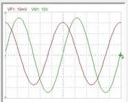
This is FF's LM1875 transient in solo. Always 10khz 10v scale 20ns. The circuit is shown bellow except the Zobel resistor became 1 ohm instead of 1k. Loaded 12 ohms

This is the transient of the composite single LM1875. Yes, no doubt the harmonic distortion should be lower, but observe how the blindness has dramatically increased. All composites I designed and used, have low presence sound, good to hear a beautiful background sounding amplifier while reading or chatting without being attracted by the music.
Attachments
Last edited:


Are all of these circuits in virtual form only, or have some been built/tested/measured/listened to?
For example, in #33 you have shown a circuit that has input zeners with a cutoff voltage of 5.3-5.4V. In real life, such a zener will start soft clipping the signal at about 3.5V. Limiting the amount of power available. Since the LM1875 is being operated now at 15dB gain, you will get more bandwidth. How much improvement is due to composite and how much due to increased feedback is not established.
If this circuit was built and tested with full measurements, would these other considerations show up?
The circuit you refer to post 33 is designed by FauxFrench. You find all the details here LM1875 in parallel configuration and used in a composite amplifier.
I don't know when I'll be able to go back home to try out anything. I have lot to realize. The only version I am curious to here its sound, is one branch V//I and the other 2×-I driven by the V, but one of the I is under the command of the error corrector. If there is no any impedance variation from 8 ohms no phase shift no distortion, than the amp is a current amplifier. Any error deviating from 8 ohms load the error corrector activates. In such amp, the current sparks first into the load in lead the voltage lags.
I don't know when I'll be able to go back home to try out anything. I have lot to realize. The only version I am curious to here its sound, is one branch V//I and the other 2×-I driven by the V, but one of the I is under the command of the error corrector. If there is no any impedance variation from 8 ohms no phase shift no distortion, than the amp is a current amplifier. Any error deviating from 8 ohms load the error corrector activates. In such amp, the current sparks first into the load in lead the voltage lags.
Are all of these circuits in virtual form only, or have some been built/tested/measured/listened to?
For example, in #33 you have shown a circuit that has input zeners with a cutoff voltage of 5.3-5.4V. In real life, such a zener will start soft clipping the signal at about 3.5V. Limiting the amount of power available. Since the LM1875 is being operated now at 15dB gain, you will get more bandwidth. How much improvement is due to composite and how much due to increased feedback is not established.
If this circuit was built and tested with full measurements, would these other considerations show up?
We have since come up to speed with the minimum closed loop gain of 10.
If one reduces closed loop gain then the gain line holds up to a high frequency for longer to a point where it starts to decline at 10 dB per decade in frequency.
Phase starts to change a decade in frequency below the point where gain declines to 0.707 of that at 1Hz. In the time domain it has a good head start.
The gainclone I built had a closed loop gain of 23. I still have this and dusted it off to check the resistor values. I think it better to have a stable amplifier rather than push the boundaries with THD figures.
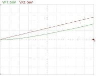
The spice model of LM1875 doesn't model the distortion, but the noise yes. To show by what factor the distortion is to be reduced by Hec, the noise reduction can give an idea.
It reduces by more than 30 times. If the distortion of a bridged is 0.02% then 0.0007% can be expected.


It reduces by more than 30 times. If the distortion of a bridged is 0.02% then 0.0007% can be expected.
Last edited:
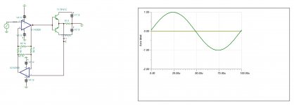
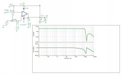
This is another idea to have correct transients, elliptic. The gain is reduced to two to get maximum NFB , the noise gain is adjusted to be over 10 but it is pushed to high frequency to form at 1Mhz a resonance with the natural cut frequency. In the input a 1Mhz notch is introduced to destroy this resonance. The result is elliptic low pass function.
The transient response now is excellent. Of course an input gain is necessary, but the LM1875 is saved.
Scope scale is 20ns.
Attachments
Last edited:
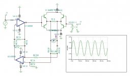
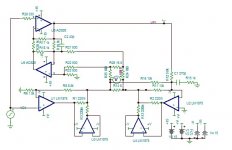
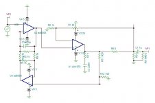
This version uses both LM1875s identical non inverting, as I noticed both on internal circuit and simulator that the negative input is not identical to the positive, this why on transients has misbehaviors. One the other hand the subtraction of the two elliptic functions results addition at high frequencies, I see about it after I add output LRs. The AD826 is one of few that has OLBW 20khz. The distortion is 2nd harmonic dominant, as it doesn't get subtracted by the bridge, the amp's distortion remains 2nd harmonic dominant.
For the error corrector, it is still differential sense and controls one branch but, It is not Hec. It subtracts the freshest input from the differential output brought to same level, and only the error is feedbacked to loop the single branch with a gain of 4. This technic is more commonly used and easier to be understood than the Hec. The AD 826 as Error amplifier is not best suited, My favorite AD8008 could be better but it wound require another power supply +/-5v. Maybe AD8610, the sound of the amplifier depends greatly upon the character of the error amplifier. As best is promised, The best it will get.
Hayk
Attachments
Last edited:
- Status
- This old topic is closed. If you want to reopen this topic, contact a moderator using the "Report Post" button.
- Home
- Amplifiers
- Chip Amps
- The LM1875 for best