Is it such a concern that the amplifier rings with such a large attached capacitance? I have measured cables that are several meters long consisting of four interwined conductors and have not measured over 10 nF of capacitance. Have you measured the capacitance of your cables to see if this is really a concern? Speaker cones tend to be inductive, and only perhaps electrostatic speakers might have a high capacitance like this.
Any suggestions please?
All of those capacitive loads are higher than will be presented to the amp even with long speaker cables, no?
The amp is ringing at that very high freq partly because it is being asked to provide gain up there. You can even see a little of it in the no-capacitive-load case. Size a small capacitance in parallel with the 22k feedback resistor to reduce the gain to unity at high freqs. A 10pF limits the feedback bandwidth (-3dB) to 723kHz and should tame most if not all of that resonance. Use an NP0/C0G ceramic or mica cap.
EDIT: I see you're using 20k in series with 47pF for this, it is not enough, remove the 20k and use the 10pF suggested. You don't want the amp gain curve to cross the open loop gain curve.
Last edited:
profdc9 said:Is it such a concern that the amplifier rings with such a large attached capacitance?
You're both right of course; In part I'm trying to better understand what is going on when the ringing occurs, and in doing so make a stable amp even at ludicrous load capacitance.jbau said:All of those capacitive loads are higher than will be presented to the amp even with long speaker cables, no?
Thanks for the suggestion. I'll try this out on the test board I'm going to build next, and see what happens.jbau said:I see you're using 20k in series with 47pF for this, it is not enough, remove the 20k and use the 10pF suggested. You don't want the amp gain curve to cross the open loop gain curve.
Cheers, Christian
With the capacitance you have attached, it's likely the kind of load that might be attached to the amplifier would be a piezoelectric element stack, so the amplifier could be useful for nanopositioning, for example. These might have the kind of capacitance that you are designing for.
You're both right of course; In part I'm trying to better understand what is going on when the ringing occurs, and in doing so make a stable amp even at ludicrous load capacitance.
Thanks for the suggestion. I'll try this out on the test board I'm going to build next, and see what happens.
Cheers, Christian
Hi, Can anyone tell me what s is in this equation from page 8 of the LM3886 datasheet?
fc = [Rf1 Rf2 (s + 1/Rf2Cf)]/[(Rf1 + Rf2)(s + 1/Cf(Rf1 + Rf2))]
This is the high frequency pole for the Rf2Cf network in parallel to the feedback resistor. I can't find any reference to what the value of s might be. Because it is added to the LHS it would have to be a relatively large number to have any effect, although that effect is to reduce the result. A value of zero just gives the answer as Rf1, which if 20k isn't a particularly high low-pass roll-off. To increase the frequency, the value of s would have to be negative.
(Perhaps I'm misinterpreting it, which is entirely likely!)
Thanks, Christian
Hi,
's' is the Laplace domain frequency variable, which can be replaced by 'jw' (w = ohmega, the frequency in radians/s) in order to evaluate the frequency response.
The equation as written is the transfer function of the Rf1/Rf2/Cf feedback network, rather than an expression of the frequency fc, and has a pole and zero as follows:
w(p) = 1 / Cf(Rf1 + Rf2)
and
w(z) = 1 / Rf2.Cf
Using the datasheet values of 20k, 20k and 50p will give:
w(p) = (1 / 50p(20k + 20k)) = 5e5 => f(p) = 5e5 / 2.pi = 79.6kHz
w(z) = (1 / 20k.50p) = 1e6 => f(z) = 1e6 / 2.pi = 159.2kHz
So there will be a closed-loop gain reduction of a factor of 2 occuring between 79.6kHz and 159.2kHz
It can be useful to see what happens at the extremes of s:
s = 0 (DC) => transfer function = (Rf1/Cf) / ((Rf1 + Rf2)/Cf(Rf1 + Rf2)) = Rf1
i.e. just Rf1 as Z(Cf) -> infinity
s -> infinity => transfer function = Rf1.Rf2.Cf.s / ((Rf1 + Rf2)Cf.s) = Rf1.Rf2 / (Rf1 + Rf2)
i.e. the parallel combination of Rf1 and Rf2 as Z(Cf) -> 0
Hope that helps!
")
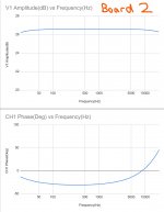
A similar question if I may: can someone in the know interpret the phase plots on these two Bode plots? I managed to get a solution working where my SDS1104XE scope can talk to my cheap Chinese signal generator (KKMoon FY6900) via my PC, so now I can run a proper Bode plot to ascertain the frequency response of the amp.
Board 2 is the second of the two original boards I built according to the schematic in the earlier post.
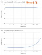
Board 3 is a new board which has different components, mainly to flatten the response which was lacking a little bass-wise previously, and to sort out the horrible ringing seen earlier (more on that in a later post).
The frequency response on board 3 looks good, and in line with what I simulated, however I'm not sure how to interpret the phase graphs. Given a near identical gain of around 26dB, board 2 has a negative phase until 8.3kHz, when it crosses 0 degrees, whereas board 3 has an entirely positive phase.
What would be the ideal phase plot for an amp like this?
Thanks, Christian
Board 2 is the second of the two original boards I built according to the schematic in the earlier post.
Board 3 is a new board which has different components, mainly to flatten the response which was lacking a little bass-wise previously, and to sort out the horrible ringing seen earlier (more on that in a later post).
The frequency response on board 3 looks good, and in line with what I simulated, however I'm not sure how to interpret the phase graphs. Given a near identical gain of around 26dB, board 2 has a negative phase until 8.3kHz, when it crosses 0 degrees, whereas board 3 has an entirely positive phase.
What would be the ideal phase plot for an amp like this?
Thanks, Christian
Attachments
Actually it suddenly occurred to me that the differences in phase are down to how I've set up my hardware - I'm using both channels of my signal generator to generate the plot - channel 1 goes to the amp, and channel 2 directly to the scope. If the two channels aren't in sync then the two waveforms being compared will be out of phase, and that's almost certainly what's going on here. Looks like I need a BNC splitter to get a more accurate plot. That's a trap for young players!
I've been doing some listening tests (hey, that's what the amp was built for!) using boards 1 and 2, set up as a stereo pair, into my Monitor Audio Monitor 2 Gold bookshelf speakers.
At first I was outputting directly from my PC's headphone jack, and there was some faint hiss from the tweeters, but going via a Topping D10s USB DAC, the amps are dead silent. I hear no hiss whatsoever even with my ear right next to the tweeters.
Sound is generally very well defined, with excellent separation and good, precise bass. I'm a bit disappointed with the mid range though, where many female vocals (think Tori Amos, Kate Bush, Stevie Nicks) sound quite harsh - to the point of being a bit painful to listen to at high volumes. Not sure what to do about that. I'll need to try the amps out on some other speakers too at some point, and do some comparisons with proper amps.
- Status
- This old topic is closed. If you want to reopen this topic, contact a moderator using the "Report Post" button.
- Home
- Amplifiers
- Chip Amps
- Another LM3886 Amp PCB