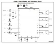
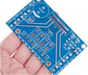
I populated a board bought from ali.. which seems to me to be using datasheet scheme. For C9, C10 I used bipolar as in datasheet (the silkscreed shows them polar). For the input caps i used some 10uF muse I had around and for C7 I used a stack of 3x1000uF. The problem is I get plenty of DC on outputs when I power it on. It lasts for a few seconds (3-4) then it disappears and the music starts playing. Any ideeas what it could be? The IC is original from digi.
Attachments
")
Thanks for input.
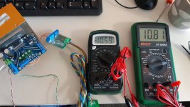
Here are some maximum readings on two outputs, 1-2 seconds after power on. This is what I get if there is an input signal. If there is no input signal then the readings go to about 1V DC. After this peak, it slowly decreases in about 40 seconds to acceptable values (<40 mV). The speakers were not connected during the readings.
Here are some maximum readings on two outputs, 1-2 seconds after power on. This is what I get if there is an input signal. If there is no input signal then the readings go to about 1V DC. After this peak, it slowly decreases in about 40 seconds to acceptable values (<40 mV). The speakers were not connected during the readings.
Attachments
Last edited:
The behaviour of it all sounds pretty normal.
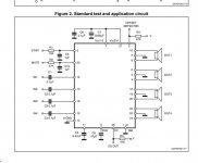
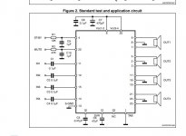
The data sheet mentions it has anti pop circuitry and I think the time constant is determined by the SVR cap on pin 11............... which is a bit confusing as two data sheets have different pin outs.
The data sheet mentions it has anti pop circuitry and I think the time constant is determined by the SVR cap on pin 11............... which is a bit confusing as two data sheets have different pin outs.
Attachments
Tried using the specified values on the inputs?
I admit I used very big caps (for this application) on inputs (10uF) only because I had them around. ...But, rising the capacitance of input caps just lowers the high pass frequenc; any dc won't pass through these caps, no matter their values (anyway, I used a smartphone headphone output as a signal source, so I think the signal is quite clean).
The behaviour of it all sounds pretty normal.
The data sheet mentions it has anti pop circuitry and I think the time constant is determined by the SVR cap on pin 11............... which is a bit confusing as two data sheets have different pin outs.
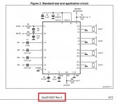
Uh, oh, that's interesting. I think the latest datashet should be more accurate - the revision date should be written somewhere (at the begining, I think) in datasheet.

- Status
- This old topic is closed. If you want to reopen this topic, contact a moderator using the "Report Post" button.
- Home
- Amplifiers
- Chip Amps
- TDA7388 - DC on output at power on