Finding the exact reason why it makes the noise might be difficult.
The muting arrangement (cap and resistor) is supposed to be to prevent these noises but I have never used an LM3886 in any projects and so can not say how good or otherwise that is.
Does it make the noise with no inputs connected and the volume control on minimum?
If it does then the noise would seem to be internal to the amp itself.
You could also repeat the above test but this time use a different method of turning the amp on and off such as a switch on a wall socket rather than the one on the amp. That might show if the noise was something external like a slow to make switch contact causing interference that then breaks through into the amp.
Have to say that in my experience pretty much all amps make noises unless they have a dedicated relay delay on the output. Adding one is easy to do and only needs a suitable relay and very few other parts.
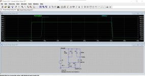
This is one. The relay is controlled by a transistor (a FET) and the delay is given by the time constant of the 470k and 47uF cap. You can alter those to get any time delay you want.
The Zener simply protects the FET.
D1 absorbs back EMF from the relay although in practice it switches to slowly for that to be an issue... but if you don't add it then folk complain")
D2 discharges the timing cap more quickly when you turn the amp off so that it is ready to work again immediately if needed.
The circuit just gets its supply from across one of the rails.
This shows the supply appearing 10 seconds into the simulation and the relay current appearing a few seconds later (the delay).
The muting arrangement (cap and resistor) is supposed to be to prevent these noises but I have never used an LM3886 in any projects and so can not say how good or otherwise that is.
Does it make the noise with no inputs connected and the volume control on minimum?
If it does then the noise would seem to be internal to the amp itself.
You could also repeat the above test but this time use a different method of turning the amp on and off such as a switch on a wall socket rather than the one on the amp. That might show if the noise was something external like a slow to make switch contact causing interference that then breaks through into the amp.
Have to say that in my experience pretty much all amps make noises unless they have a dedicated relay delay on the output. Adding one is easy to do and only needs a suitable relay and very few other parts.
This is one. The relay is controlled by a transistor (a FET) and the delay is given by the time constant of the 470k and 47uF cap. You can alter those to get any time delay you want.
The Zener simply protects the FET.
D1 absorbs back EMF from the relay although in practice it switches to slowly for that to be an issue... but if you don't add it then folk complain
D2 discharges the timing cap more quickly when you turn the amp off so that it is ready to work again immediately if needed.
The circuit just gets its supply from across one of the rails.
This shows the supply appearing 10 seconds into the simulation and the relay current appearing a few seconds later (the delay).
Attachments
The relay is the main item. I think your amp from memory used an 18-0-18 transformer and so has around -/+25 volt rails.
So the relay example here is a 24v dc type and the contacts are DPDT (double pole double throw just like a switch).
If you can not get a 24v one then we can use a 12v type and just add a series resistor to loose the voltage.
You need a power FET and even a little 2N7000 type would be ideal.
https://cpc.farnell.com/on-semiconductor/2n7000/mosfet-n-logic-to-92/dp/SC06951
The timing cap can be a 47uF or 100uF electrolytic of 16v or higher rating and you need a resistor to go with it, lets say a choice of 150k, 270k and 470k. Those values will let you experiment with the delay times.
You need two 1N4004 or IN4007 diodes (any common diodes of 50 volt or higher will do) and one 12 volt Zener diode of low wattage.
https://cpc.farnell.com/nxp/bzx79-c12/diode-zener-500mw-12v/dp/SC05705?st=12 v zener
One thing to consider is how you will mount all these. The circuit is so simple it could be made point to point and secured by soldering it to the relay pins.
You need to mount the relay in some way though.
Attachments

- Home
- Amplifiers
- Chip Amps
- Complete novice alert! *don't read if easily annoyed by stupid questions*