Not done much what with real life getting in the way ") but I'm intending to build it as I have drawn it so that I can troubleshoot it slightly more easily. Well, that's the theory.
but I'm intending to build it as I have drawn it so that I can troubleshoot it slightly more easily. Well, that's the theory.
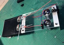
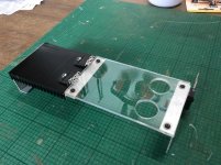
I've mounted the chips onto the heatsink and joined this to a piece of perspex which has the holes for the two large caps drilled into it. Then the rectifier is fixed to the end 'leg' that doubles as another heatsink.
but I'm intending to build it as I have drawn it so that I can troubleshoot it slightly more easily. Well, that's the theory.An externally hosted image should be here but it was not working when we last tested it.
I've mounted the chips onto the heatsink and joined this to a piece of perspex which has the holes for the two large caps drilled into it. Then the rectifier is fixed to the end 'leg' that doubles as another heatsink.

Bugger!
Is this better?...
Is this better?...
An externally hosted image should be here but it was not working when we last tested it.
Last edited:
Nope
Just attach them in the proper way. That way they are here forever:
How to attach images to your posts.
Just attach them in the proper way. That way they are here forever:
How to attach images to your posts.
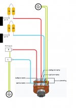
 OK, and remember to use the bulb tester and to check the DC conditions before thinking about connecting a speaker.
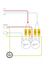
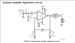
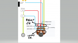
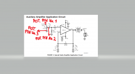
Your wiring diagram in post #91 is confusing and/or wrong because you displayed the left potentiometer as a front image while you displayed the right potentiometer as a rear image. The wiring diagram would be ok if the left potentiometer is displayed as well as the right (from rear). Please, do not connect speakers at this stage...
how to wire a stereo potentiometer - Google Search
how to wire a stereo potentiometer - Google Search
Okay I've wired up just the left channel. When I turn it on (using DBT of course) the bulb stays lit and I get a buzzing through the speaker. I notice that I have continuity for both the positive and the ground through the speaker terminals. Obviously this isn't right.
Is it a very loud buzzing?
If you disconnect the speaker does the bulb go out or dim?
If the bulb does go dim then what DC voltage do you see between the speaker terminals?
(you will measure continuity all over the place as you will be reading through the internals of the chip. If there were a short across the speaker output then you wouldn't get the buzz)
- Home
- Amplifiers
- Chip Amps
- Complete novice alert! *don't read if easily annoyed by stupid questions*