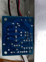
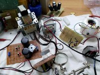
It is difficult working from pictures.
Begin at pin 1 and look really really carefully at your board and make sure it only goes to the parts it is supposed to go to. Follow each component lead and check check check.
Do the same for every pin.
Also do quick resistance checks from each pin to its neighbours and make sure you have no accidental shorts.
And another way to approach this is to remove the chip and then power the board up. Apart from the supplies you should see no voltage on any other point.
You can also check the connectivity (components) between the pins with the power removed and also make sure you read the expected resistance between the appropriate pins.
You can also check the connectivity (components) between the pins with the power removed and also make sure you read the expected resistance between the appropriate pins.
YOU MUST FOLLOW INSTRUCTIONS
You were told:
Switched OFF is switched OFF, period, not "for 22k"
It´s a too low value, we would expect 22k or some similar high value.
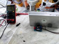
Are you measuring with power supply OFF, ZERO Volts on rails?
UNPLUG power supply from mains, just in case you forget to turn it OFF.
I will trust pin 2 to pin 4 measurement when I see it.
Pin to pin themselves, not solder pad to solder pad. Not the same.
Your test METHODs are unreliable and maddening.
YOU MUST MEASURE EVERYTHING WITH POWER OFF, SUPPLY UNPLUGGED FROM MAINS.
EDIT:L'inglese è la lingua ufficiale del Forum ma poiché abbiamo problemi di traduzione e comprensione, puoi scrivere anche in italiano
Ancora di più il post principale in inglese
(English is Forum official language but since we seem to have translation and comprehension problems you can *also* write in Italian.
Although your main answer must still be in English.)
Repeat and repost results WITH POWER OFF
NO NO NO NO NOHello everyone, here are the measurements: pin 4 is connected to 2 through a 22k resistor measuring between 2 and 4 with power supply switched on from zero,
You were told:
1) turn amp OFF, wait until rails are ZERO.
If after 2 minutes you still have some residual voltage, short them to ground with a piece of wire.<<< this is to GUARANTEE supply rails are ZERO volts
POST THIS RESULT.2) measure resistance from pin 4 to pin 2 using the resistance scale (200k), straight from chipamp pin to pin, post result.
What does this mean?with power supply switched off for 22k.
Switched OFF is switched OFF, period, not "for 22k"
You mean you measure 4.7 ohm?from pin 2 to ground I give 4.7 ohm.
It´s a too low value, we would expect 22k or some similar high value.
Are you measuring with power supply OFF, ZERO Volts on rails?
UNPLUG power supply from mains, just in case you forget to turn it OFF.
In theory it is connected.the feedback resistor (22k) is connected between 2 and 4.
I will trust pin 2 to pin 4 measurement when I see it.
Pin to pin themselves, not solder pad to solder pad. Not the same.
You are giving 2 DIFFERENT results for the SAME measurement.between pin 2 and the ground it gives me continuity (short), but also a resistance of 4.7 with the power supply off.
Your test METHODs are unreliable and maddening.
YOU MUST MEASURE EVERYTHING WITH POWER OFF, SUPPLY UNPLUGGED FROM MAINS.
EDIT:L'inglese è la lingua ufficiale del Forum ma poiché abbiamo problemi di traduzione e comprensione, puoi scrivere anche in italiano
Ancora di più il post principale in inglese
(English is Forum official language but since we seem to have translation and comprehension problems you can *also* write in Italian.
Although your main answer must still be in English.)
Repeat and repost results WITH POWER OFF
Last edited:
We can and will, as long as we get reliable measurements.
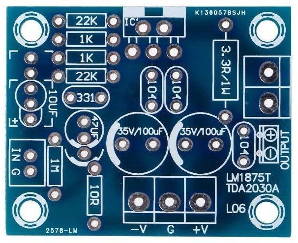
Plan B would be to rebuild amp on a commercial PCB which supposedly is electrically correct and with good layout.


Full kit description:
TDA2050 original from STM, mono amplifier - Kit-Amp

You can build it WITHOUT a PCB!!!!!
TDA2030 IC circuit amplifier without pcb - YouTube

which in your case I recommend:
1) it is very didactic
2) no board error possible
3) I bet it will work on first try.
That way too large stripboard, besides huge size creating lots of dangerous antennas, is way less reliable than standard PCBs and way more error prone, because you MUSY cut tracks yourself, easy to miss one cut.
I love veroboard and in fact printed a few spare ones myself (the real one is hard to find here) for one off quickies, go figure.
I don´t even drill them , but build with copper tracks up, and blob soldering to them, poor man´s SMT
Plan B would be to rebuild amp on a commercial PCB which supposedly is electrically correct and with good layout.
Full kit description:
TDA2050 original from STM, mono amplifier - Kit-Amp
You can build it WITHOUT a PCB!!!!!
TDA2030 IC circuit amplifier without pcb - YouTube
which in your case I recommend:
1) it is very didactic
2) no board error possible
3) I bet it will work on first try.
That way too large stripboard, besides huge size creating lots of dangerous antennas, is way less reliable than standard PCBs and way more error prone, because you MUSY cut tracks yourself, easy to miss one cut.
I love veroboard and in fact printed a few spare ones myself (the real one is hard to find here) for one off quickies, go figure.
I don´t even drill them , but build with copper tracks up, and blob soldering to them, poor man´s SMT
Last edited:
I would also suggest building it point to point without a PCB, that way we can all see exactly what is connected where. The way you build it is impossible to figure out the connections.
There is no need to power up the circuit until we've had a look, and then you can go and build it in your own style.
There is no need to power up the circuit until we've had a look, and then you can go and build it in your own style.
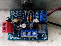
Better still, just buy the LM1875 mono boards on ebay etc as they are cheap. There's a thread on these and saves a lot of hassle. Many builders have found this to be a good little amp especially if you only use the PCB and obtain genuine components plus it's easy to build.
eBay mono LM1875 kit
eBay mono LM1875 kit
ciao ragazzi e grazie ancora a tutti per la pazienza e cortesia.
ho intenzione di fare ,senza sbagliare possibilmente, quei controlli
che mi ha chiesto JMFahey e prima ancora mooly.
lo so che è molto piu' facile usare le pcb gia fatte(ne ho ordinata qualcuna),ma voglio provare a vedere se riesco a capire dove sbaglio.
grazie ancora e scusatemi.
ho intenzione di fare ,senza sbagliare possibilmente, quei controlli
che mi ha chiesto JMFahey e prima ancora mooly.
lo so che è molto piu' facile usare le pcb gia fatte(ne ho ordinata qualcuna),ma voglio provare a vedere se riesco a capire dove sbaglio.
grazie ancora e scusatemi.
hello guys and thanks again to everyone for your patience and courtesy.
I'm going to do, without possibly making mistakes, those checks
that JMFahey asked me and before that mooly.
I know that it is much easier to use the pcbs already made (I have ordered some), but I want to try to see if I can understand where I am wrong.
thanks again and sorry.
I'm going to do, without possibly making mistakes, those checks
that JMFahey asked me and before that mooly.
I know that it is much easier to use the pcbs already made (I have ordered some), but I want to try to see if I can understand where I am wrong.
thanks again and sorry.
2) misurare la resistenza dal pin 4 al pin 2 utilizzando la scala di resistenza (200k), direttamente dal pin del chipamp al pin, dopo il risultato.
22k
- Status
- This old topic is closed. If you want to reopen this topic, contact a moderator using the "Report Post" button.
- Home
- Amplifiers
- Chip Amps
- LM1875 non funziona