I was thinking on ground loops inside the amplifier case. If you have hum try to lift ground on one side of channel input wire, leave only one ground to the inputs of the amplifiers (if chinch common is interconnected on inputs). Also you have VU meter driver circuit, you should be careful about ground signal on that circuit, only one reference wire should be.
Hi PitBull.
I will try to reduce the ground wires as much as possible, meanwhile i am struggling to find a good cable for those connections, I used UTP cable for this project but but there must be a greater choice for this intent, please enlighten me
") .
.Thank you for the support.
both look good,but heatsink one looks like it means more business!!
I totally agree with you, thanks for the comment
AudioTag, there is no need to search another type of wire, this UTP is absolutely fine (I also use this type of wire inside of my amplifiers), pull out one of four pairs and put it away from transformer, link it that way to your input of the amplifiers (I didn't notice, are you using input regulation-potentiometer?) from the chinch connectors.
Pair means blue/white-blue wires twisted together, or brow, or orange, or green combination., in total 8 wires, but 4 pairs
If you are using potentiometer for input level regulation, also try to avoid transformer on your routing of the input wires.
You will be surprised with the sound, I was.
Today I like sound of the GainCard amplifiers and many others who I represented my work.
Pair means blue/white-blue wires twisted together, or brow, or orange, or green combination., in total 8 wires, but 4 pairs
If you are using potentiometer for input level regulation, also try to avoid transformer on your routing of the input wires.
You will be surprised with the sound, I was.
Today I like sound of the GainCard amplifiers
and many others who I represented my work.Im using a multistrand utp cable but i will try to find some high quality cat6 cable and since all ground input cables are connected i will reduce the wires as much as possibel and avoid the near transformer rounting, my amplifier case is a bit tight for that job though.
Can you please post some pictures or links of your builds ?
And for the input regulation i tried some potenciometer of 50k and it was not very effective. can you please tell me if the 10k will be more smoth ?
Take care.
Can you please post some pictures or links of your builds ?
And for the input regulation i tried some potenciometer of 50k and it was not very effective. can you please tell me if the 10k will be more smoth ?
Take care.
Last edited:
If I use input regulation I have 20 (22)kohm log, (log= logarithmic, be careful with markings A or B because there are different in different part of the world, I also had problems with orderings from China), at the input of GainCard amp.
As I mentioned, I have 3 builds, one is in old Technics amp (as replacement of the burned amp IC) 2x LM4780 parallel, now is at my home because of some switch replacement (build for my friend) and I will take some pictures and show you. 10kohm will be OK, lower value of the resistance is good, but your preamp should be capable of driving it. I use opamp LM4562 as preamp.
Second one, finished, but not representative as yours, large case, dual mono config 2xLM4780 parallel without input regulation ( I only have pictures of the outside), when it will be returned from friend I will try to take pictures of the inside.
And the third one is currently not fully finished because I would like to make fully integrated one with input selector and preamp, so this pictures will not be published. Config is 2x LM3886 in parallel, stereo, with 300VA toroid, something similar to your build.
I am currently at the job (instead of morning news I read diyaudio forum), so if there will be time I will take pics of the technics inside and show you.
One hint, which is many times mentioned on this forum, when you make parallel amps, resistors for the return path which defines amplification, should be 0.1% tolerance. I don't know source of your boards, but mine are from china and I replaced these resistors with known manufacturer and mentioned tolerance.
Regards,
dr
Meanwhile i bypassed the volume control and use this build as just an amplifier, im using the Denon AVRX-3500h as a pre amp, since Denon built in power amp sucks.
Can you show me the preamp board you using ? maybe some link ?
When you have time, please post them here ;D
Have a nice weekend.
Can you show me the preamp board you using ? maybe some link ?
When you have time, please post them here ;D
Have a nice weekend.
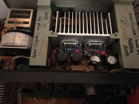
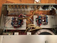
These pictures are my work, name of files describe it.
AMP pictures shows how twisted pair wires are placed inside the case. I showed these pictures because I don't have some final work. They are from still development phase (I wrote that these will not be published).
Preamp is based on X-Altra Mini One Line premplifier from hifi sonix.
AMP pictures shows how twisted pair wires are placed inside the case. I showed these pictures because I don't have some final work. They are from still development phase (I wrote that these will not be published).
Preamp is based on X-Altra Mini One Line premplifier from hifi sonix.
Attachments
Last edited:
These pictures are my work, name of files describe it.
AMP pictures shows how twisted pair wires are placed inside the case. I showed these pictures because I don't have some final work. They are from still development phase (I wrote that these will not be published).
Preamp is based on X-Altra Mini One Line premplifier from hifi sonix.
Nice work on the technics, you added a toroidal ?, it must weight a ton now ;D
Your heatsink in LM3886 project seem insufecient though, you bridged them, im curious of the schematic, where you get that bridge config ?
Thank you for the fotos.
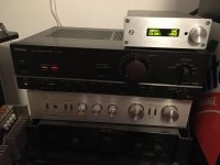
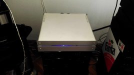
And here is outside picture of my GainClone case (it's not recent), dual mono config with parallel LM4780. Today's picture I don't have, but when it will be returned I will make them.
Nice case,
cant wait to see final picture ;DTake care.
AudioTag, in Technics both channels work in parallel, not bridged, my goal was to achieve more current on the output for low ohmic loudspeakers (4 ohm) on relatively high voltage for this amp (+/- 36V without regulation, under load it will be little lower). Similar concept to your triple parallel config which is a bit better. I didn't fully understand why you have two amps with two VUs on the front, is it stereo combination, or parallel/bridge. My logic says that there are two stereo with 3 ICs in parallel in one case.Nice work on the technics, you added a toroidal ?, it must weight a ton now ;D
Your heatsink in LM3886 project seem insufecient though, you bridged them, im curious of the schematic, where you get that bridge config ?
Thank you for the fotos.
Torodial transformer in this amp doesn't serve as main transformer, original Technics serves for it. Torodial is here to lower primary voltage on primary of the Technics transormer, it is in autotransformer connection. So toroid transformer doesn't have equal power like Technics, it has nominal current of the Technics primary current at the secondary side wich lowers the primary voltage of the Technics transf. This amp has about +/-45Vdc which is too high for the GainCard amp. Minimal invasion was done inside of Technics case, everything is adopted to replace original IC and AA clas in the output stage and results are estonish good. For the control of the output relay it is incorporated uPC1237 circuit to switch the output relay and monitor DC output.
Last edited:
Greetings see these links:Hello. What glue did you use for the heatsinks?
Thermal silicone glue ST922 for radiator 5g - Audiophonics
Attachments

AudioTag, in Technics both channels work in parallel, not bridged, my goal was to achieve more current on the output for low ohmic loudspeakers (4 ohm) on relatively high voltage for this amp (+/- 36V without regulation, under load it will be little lower). Similar concept to your triple parallel config which is a bit better. I didn't fully understand why you have two amps with two VUs on the front, is it stereo combination, or parallel/bridge. My logic says that there are two stereo with 3 ICs in parallel in one case.
Torodial transformer in this amp doesn't serve as main transformer, original Technics serves for it. Torodial is here to lower primary voltage on primary of the Technics transormer, it is in autotransformer connection. So toroid transformer doesn't have equal power like Technics, it has nominal current of the Technics primary current at the secondary side wich lowers the primary voltage of the Technics transf. This amp has about +/-45Vdc which is too high for the GainCard amp. Minimal invasion was done inside of Technics case, everything is adopted to replace original IC and AA clas in the output stage and results are estonish good. For the control of the output relay it is incorporated uPC1237 circuit to switch the output relay and monitor DC output.
Good morning my friend.
The ics on the technics are LM3886 ? seems like other ones, LM 4780 ?
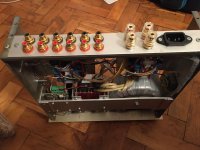
The bridge config i was mentioning is on the foto named AMP_Gainclone2cr.jpg
Answering your doubt about my system:
I have a pair of bi-amp capable speakers that need a good amount of power, The SVS Ultra Towers. so i use an amplifier for each speaker. 2 modules of 3 x LM3886 for each speaker. I can use the amplifiers for stereo independently but i chosen this bi-amp config because i needed more power.
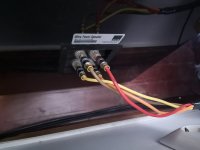
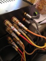
See pics of cables, of course the vu meters measure equal because i use one channel for each amp.
Attachments
Last edited:
As you know LM4870 are 2xLM3886 in one case.
On AMP pictures there are 2 modules of LM3886 in parallel also.
I prefer parallel combo more then bridge as described before, more current on the output (2x11A peak).
Heatsink should be OK for that use.
My modules are cheap one and I should upgrade it with some zoebel circuit on each chip and added output resistor for parallel operation. As you can see between two modules are resistors and zoebel, wire for parallel connection so speaker output is taken from one module.
Twisted pair is between two inputs but not connected ground wire on one side, usually output side, because there are ground wires for the power and easily ground loop is possible.
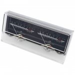
I am also interested how did you calibrate your VU meters?
You wrote that they are now connected to the output of the amp.
Are they circuit DC passed, or have some DC blocking caps?
I have some hint for you to calibrate them easily to see real power of output. If you didn't calibrate I can advise.
You wrote that they are now connected to the output of the amp.
Are they circuit DC passed, or have some DC blocking caps?
I have some hint for you to calibrate them easily to see real power of output. If you didn't calibrate I can advise.
Hello.
Yes i would like to learn how to calibrate the vu meters accordingly to DB. This vu meter can work in ac or dc 12v to 15v, I’m wearing a AC led transformer to power the vu meter controller that powers the vu meters the backlight leds also
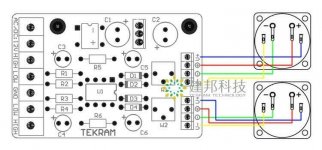
I send you some pictures and schematic attached.
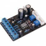
① LOW, GND, LOW: It is the driver board’s Low-level signal input terminal, you can connect it to CD Player/PC sound card/preamp, etc, audio signal ,LOW、GND、LOW Corresponding to: left channel 、GND、right channel (Adjusting two Potentiometer to control the pointer swing.if it with full Signal but the pointer swing not reach your expectation or the Volume change to lower or distortion,you can move R2、R3 resistor)
②HIGH、GND、HIGH:
It is the driver board’s high-level signal input terminal,you can connect it to the signal via amplifier,the two HIGH terminal corresponding to amplifier’s two RED terminal, GND corresponding to one of the black amplifier terminal.
2.Driver board output:
V+, V-, Terminal: It is the backlight,support 2 set 12v backlight terminal,when connecting pls note the positive or negative electrode
+,-,Terminal: it is the driver board’s output terminal ,connect it to VU meter’s “+”“-”
3.Power supply
Woking voltage:AC/DC 12-15V (we recommend adopting the independant power supply)
Rated power:3W
Yes i would like to learn how to calibrate the vu meters accordingly to DB. This vu meter can work in ac or dc 12v to 15v, I’m wearing a AC led transformer to power the vu meter controller that powers the vu meters the backlight leds also
I send you some pictures and schematic attached.
① LOW, GND, LOW: It is the driver board’s Low-level signal input terminal, you can connect it to CD Player/PC sound card/preamp, etc, audio signal ,LOW、GND、LOW Corresponding to: left channel 、GND、right channel (Adjusting two Potentiometer to control the pointer swing.if it with full Signal but the pointer swing not reach your expectation or the Volume change to lower or distortion,you can move R2、R3 resistor)
②HIGH、GND、HIGH:
It is the driver board’s high-level signal input terminal,you can connect it to the signal via amplifier,the two HIGH terminal corresponding to amplifier’s two RED terminal, GND corresponding to one of the black amplifier terminal.
2.Driver board output:
V+, V-, Terminal: It is the backlight,support 2 set 12v backlight terminal,when connecting pls note the positive or negative electrode
+,-,Terminal: it is the driver board’s output terminal ,connect it to VU meter’s “+”“-”
3.Power supply
Woking voltage:AC/DC 12-15V (we recommend adopting the independant power supply)
Rated power:3W
Attachments
Huh, I thought on direct current pass on input of your low/high signal.
As I can see it is probably DC blocked, so we can't do simple adjust by internal power supply of the amplifier with simple connection to power supply rail. If it is not DC blocked, if you connect input wire to positive rail it will show something and it will remain on some value. After that adjust the value between +3 and +6dB.
Your VU should show 0dB when you reach full RMS power. The VU meter works by input voltage, so you need to put peak voltage to the input and adjust the level accordingly.
You have your reference GND which is common for both channels (maybe best place to take single GND from power supply board for the VU board). If I understood correctly you have separate transformer for supply of the VU board, which is good, so you can't mess up with grounds.
Amplifier is capable of delivering peak power which is +3dB, when it is? when amp output reaches near maximum of your + or - V of your amplifier power supply.
Short time connection to positive or negative rail voltage should simulate pulse (or some ac signal) on your input which will be shown by VU, needle should go between +3dB and +6dB, adjust your potentiometer to show value between these numbers (better closer to +3dB).
Second option; I assume that you don't have dummy resistor of 8ohm/100W, so I don recommend adjustment by sinus signal below 400Hz and measuring RMS signal on output according to the supply voltage (when you do that way you should calculate maximum RMS voltage, positive rail voltage measured by voltmeter-approximately 2V and then divided by square root of 2, then you have RMS value which is equal your RMS power which is possible to measure by the measuring instrument-DVM). For this last task you should have audio generator (or android phone with app) and enough mV (or 1V) on output of your preamp, to achieve maximum power on output of your amp, when you achieve this, you can adjust your VU to 0dB. This measurement shouldn't be long, because amp is not generator for delivering energy, 15-30 seconds what is enough to adjust VU per channel.
Hope that first option isn't complicated, so with short connection of VU high input wire to positive or negative rail of power amp supply will help to adjust the VU. Do that channel by channel.
Last edited:
Very nice amps. The 3886 when made properly can sound fantastic, well beyond what you might think seeing the price. I am using custom PCBs with Beyschlag MELF resistors and (almost all) SMT components. The whole board is 30x50mm and the only component not mounted on it is the LC output network, which I prefer putting at the output terminal.
Re your vu meter, it is supposed to indicate power, not voltage. Normally it used in preamps and the output load is assumed at 600 ohms (so, dBU) but in power amplifiers you cannot assume a constant load under any circumstances. Also, if you set the meter to 0dB at say 8 ohm clip point, you will never be able to see it moving much at all.
I would recommend you set the level such that 0dB corresponds to 4W into 8 ohms. That would work out to about 5.5V, and you can actually get some movement. If you set it to clipping at 8R, the meter won't move past -10dB, at least not a lot. With 88dB/W/m speakers this translates into a comfortable listening level 2m away.
The other way to do it is set to a reference output level (say 80dB at listening position), but that would be valid only for one specific speaker system. Note that sag in the output as the level goes up, will mean the vu meter will never be actually accurate.
Sangram, you are missed somethnig, where is current input on that VU driver board, I see only voltage input, which are insufficient for power measuring.
VU meter driver board may have logharitmic scale to drive properly needle on instrument, so your comment is not adequate.
Calibrating with lower voltage level asks for some calculation. AudioTag will tell us is he ready for such thing.
Maybe it is difficult to understand what I wrote, but this is simplest way to adjust measuring equal to what amplifier can do.
Whitout knowing what is power supply voltage you can't have proper indication.
Is the dB scale equal for voltage reference, or for power reference? Think about it.
What is your reference wattage of this amp?
What is your reference voltage for this amp?
How you calculate dB for voltage and how you calculate for power?
Or you will assume -10% as reference output voltage (taking into lower value of voltage because of transistor Vce drop and possible ripple due high load) for lowest power gridvoltage and then calculate, but you need to take into account how much is higher or lower ac voltage on your transformer.
For your case with lower value it is possible to implement my second method, but you need the calculate what is voltage on the output which will show proper dB.
- Status
- This old topic is closed. If you want to reopen this topic, contact a moderator using the "Report Post" button.
- Home
- Amplifiers
- Chip Amps
- Building LM3886 Amplifiers