Tom is saying that You cannot get more than ~22Vrms, with +_35/36V DC rails, from an LM3886.
22Vrms^2/4ohm = ~120W. Produced on 4ohm!!!
On any number of chips.. It does not matter. You should raise the DC rail voltage for more. But You will get catastrophic consequences with a too high DC rail..
That's all.
22Vrms^2/4ohm = ~120W. Produced on 4ohm!!!
On any number of chips.. It does not matter. You should raise the DC rail voltage for more. But You will get catastrophic consequences with a too high DC rail..
That's all.
Should add: plus, going to the max, there will be clipping, unavoidably. The circuit do not contain clipping control, and the chip itself is not too 'friendly' when clipping.
So even that 120W is not really that good served.
I am using a similar amp, double current pump, that is two 3886 chips per side - - +_36V rails - so very similar to Your setup.
I have clipping control built in, which limits a bit earlier. I am using it on 4ohm drivers, and get out of it a good ~95W power.
That is reality, not marketing..
But. Those ~almost 100W are real high quality, I would never complain!!
Ciao, George
Last edited:
On the contrary, since the amplifier is just "that thingie between power supply and speakers" (Enzo [TM]) to which I strongly agree, my personal view is that "the better the Power Supply the better the end results"
Higher current reserve (higher capacitance) can only help, can´t even imagine how that could hurt.
Those claiming otherwise have only subjective opinion to back it and even so, not much agreement on that.
Higher current reserve (higher capacitance) can only help, can´t even imagine how that could hurt.
Those claiming otherwise have only subjective opinion to back it and even so, not much agreement on that.
On the contrary, since the amplifier is just "that thingie between power supply and speakers" (Enzo [TM]) to which I strongly agree, my personal view is that "the better the Power Supply the better the end results"
Higher current reserve (higher capacitance) can only help, can´t even imagine how that could hurt.
Those claiming otherwise have only subjective opinion to back it and even so, not much agreement on that.
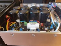
Thank you, i was about to remove all the capacitors in my build
, hehe.joking, i have 4 Elna 80V 10000uf capacitors for each amp module, you think its enouth or to much ?
Last edited:
I have 80mF in my amp, but would go higher willingly..
And what amp are you using ? 1000 W ?
Attachments
Last edited:
I thought about those capacitors but the cost would be 3 times bigger:
MUNDORF MLYTIC AG Capacitor 80V 10000μF - Audiophonics
You think they are worth ?
MUNDORF MLYTIC AG Capacitor 80V 10000μF - Audiophonics
You think they are worth ?
Attachments
Last edited:
What to say.. It is always that last fine step with price multiplication..
Though would like to underline that I had built very good sounding FE/ EVO amps with the standard BOM capacitors (Vishay) as well.. Other parameters count a lot as well, all should be kept in proportion.
Though would like to underline that I had built very good sounding FE/ EVO amps with the standard BOM capacitors (Vishay) as well.. Other parameters count a lot as well, all should be kept in proportion.
I built 2 x LM3886 amplifiers and was sadly disappointed by their sonic quality, there are far better amplifiers out there.
Try building one and see what you think.
They are OK for anyone building on a budget.
Have you tried it in transconductance configuration? Totaly different animal.
@AudioTag,
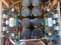
OK, I understand that you are using one pair for the signal and other one for VU input, but I see that you put it orange (orange and orange/white together) for let say minus and blue (blue and blue/white together) for signal, that is not correct, so you don't have twisted pair which eliminates unwanted noise. Twisted pair means blue for signal and blue/white for GND of the signal. At your second attempt, signal wires are also too close to the transformer and you pick the 50Hz noise. Put it at least 5cm from transformer (also signals for the VU).
Did you take measures against ground loop (you have one transformer, one rectifier and common ground for both amplifiers)?
I have 3 builds with lm3886 in parallel, I will say that sound is very good, there is no need to build something else.
AudioTag, resolve the wires for the input and you'll be surprised with sound details and quality. It has enough power with 3 chips in parallel for low ohm speakers (4 ohm, impedance may fall below that when music is playing).
This combination with unregulated power supply +/-36V will give you about 120W/4ohm, so it is well enough for home.
@AudioTag,
OK, I understand that you are using one pair for the signal and other one for VU input, but I see that you put it orange (orange and orange/white together) for let say minus and blue (blue and blue/white together) for signal, that is not correct, so you don't have twisted pair which eliminates unwanted noise. Twisted pair means blue for signal and blue/white for GND of the signal. At your second attempt, signal wires are also too close to the transformer and you pick the 50Hz noise. Put it at least 5cm from transformer (also signals for the VU).
Did you take measures against ground loop (you have one transformer, one rectifier and common ground for both amplifiers)?
Greetings Pitbul.
I will rewire my input cables acording to your advice and as far from possible from transformer, thank you for the advise.
As concerning to groundloops i simply dont use ground in my stereo devices, because all my AC network is coming from a isolation/ galvanic Transformer 220v - 220V. that was the only way to eliminate ground loops forever, i had that issue even b4 building this amplifiers.
Damn its so great to be able to share ideas with people who know so much
Ground Loop Isolator, Galvanic Isolation Tranformer & Ac Filter - YouTube
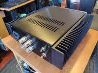
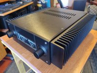
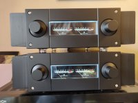
great job with the enclosures Audi tag,looks proper professional job..
Hi BrodJack.
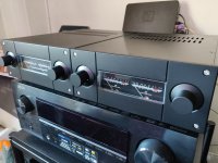
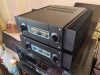
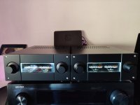
Thank you very much, i tried to make it as nice as possible, you think it looks better with the heat sink or without ?
Pictures:
Attachments
I was thinking on ground loops inside the amplifier case. If you have hum try to lift ground on one side of channel input wire, leave only one ground to the inputs of the amplifiers (if chinch common is interconnected on inputs). Also you have VU meter driver circuit, you should be careful about ground signal on that circuit, only one reference wire should be.As concerning to groundloops i simply dont use ground in my stereo devices, because all my AC network is coming from a isolation/ galvanic Transformer 220v - 220V. that was the only way to eliminate ground loops forever, i had that issue even b4 building this amplifiers.
both look good,but heatsink one looks like it means more business!!Hi BrodJack.
Thank you very much, i tried to make it as nice as possible, you think it looks better with the heat sink or without ?
Pictures:
- Status
- This old topic is closed. If you want to reopen this topic, contact a moderator using the "Report Post" button.
- Home
- Amplifiers
- Chip Amps
- Building LM3886 Amplifiers