This is my first post. I apologize in advance for my extreme ignorance.
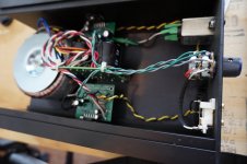
I recently bought an amp that I thought might be a shortcut to gainclone fun. See first picture. It cost less than a bare toroidal from partsexpress.
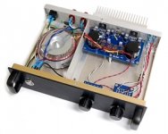
My goal is to build something like what's in the second picture.
I don't yet read circuit block diagrams well, so I hoped that by starting with a complete amp, I could just connect up an eBay input selector and be done (in a new chassis).
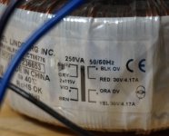
However, this amp has some hiss, and when I check the voltage at the amplifier, I read 45.7 volts. Am I right that this is too much power? The transformer has 30 volt secondaries.
If I'm right, should I try to modify the psu to drop the voltage? Or buy new amplifier boards? (e.g. ebay mx50se)?
Thanks for your help, and my apologies if asking questions like this straight off is not ok.
I recently bought an amp that I thought might be a shortcut to gainclone fun. See first picture. It cost less than a bare toroidal from partsexpress.
My goal is to build something like what's in the second picture.
I don't yet read circuit block diagrams well, so I hoped that by starting with a complete amp, I could just connect up an eBay input selector and be done (in a new chassis).
However, this amp has some hiss, and when I check the voltage at the amplifier, I read 45.7 volts. Am I right that this is too much power? The transformer has 30 volt secondaries.
If I'm right, should I try to modify the psu to drop the voltage? Or buy new amplifier boards? (e.g. ebay mx50se)?
Thanks for your help, and my apologies if asking questions like this straight off is not ok.
Attachments
Last edited:
Welcome to diyAudio Stefan ")
Your 30 volt transformer (so a 30-0-30) is really to high. The DC voltage you get when it is rectified and smoothed is 30 multiplied by 1.414 which is 42 volts. Your 45.7 volts is higher because the transformer is only lightly loaded.
You are right on the absolute maximum voltage for the LM3875 and that value is for no signal conditions.
Ideally you want something like a 25-0-25 volt ac transformer (or even a little lower) to give good reliability. That would give DC rails of around -/+36 volts DC. That would be plenty.
The hiss probably would not be altered by different voltages though... so that is something else. I've no experience how quiet these amps should be. Also your speaker sensitivity will play a part in how noticeable hiss is.
Good luck with the amp
Thanks for your reply. Are mods to the power supply an option here? Or are there other (inexpensive) amp boards available that would thrive on 45 volts?
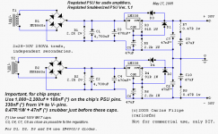
I've attached a picture of a circuit from decdun.me.uk, that appears to show a 30-0-30 AC input with a 30-0-30 DC output. Would this work for my amp? Or would I be in way over my head, even with the help of some electronics (not hifi) people at my local makerspace?
A third option would be to buy a new toroidal, as you suggest. But they are expensive, and if I (or the previous owner) have been oversupplying my chips, they might already be damaged?
Attachments
Ok. I'm thinking that since this amp has probably been used quite a bit with the high voltage, there's little harm in continuing to use it. It was used in a classroom setting, with no power switch!
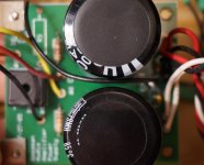
Anyway, I'm now trying to sort out the hum, and discovered more of a mess. This design has no chassis grounding, and it looks like all the grounds are daisy-chained to the house grounding.
I've attached my attempt to trace out the grounding scheme as I understand it. Apologies for my ignorance of circuit drawing conventions.
Is there any use trying to salvage this? If/when I put this amp in a new chassis, how complicated would it be to convert to a star grounding scheme?
p.s. am I lucky that the amp didn't have a chassis ground, with the +30 v wires from the transformer connecting to the power PCB's ground? Or does the AC power there not care which wire is which. (I'm pretty new to this).
Attachments

Thanks for your reply. Are mods to the power supply an option here? Or are there other (inexpensive) amp boards available that would thrive on 45 volts?
I've attached a picture of a circuit from decdun.me.uk, that appears to show a 30-0-30 AC input with a 30-0-30 DC output. Would this work for my amp? Or would I be in way over my head, even with the help of some electronics (not hifi) people at my local makerspace?
A third option would be to buy a new toroidal, as you suggest. But they are expensive, and if I (or the previous owner) have been oversupplying my chips, they might already be damaged?
Its not really practical to try to lower the voltages because of the higher currents involved. Although its easy to make a regulator to drop the voltage, the problem is that the regulator will get very hot as you turn the volume up.
If it drops 45 volts down to 30 then 15 volts is dropped across the regulator. If you now pull say 3 amps from that supply then the regulator dissipates 15*3 which is 45 watts of 'wasted power'. Just not practical.
Ok. I'm thinking that since this amp has probably been used quite a bit with the high voltage, there's little harm in continuing to use it. It was used in a classroom setting, with no power switch!
Anyway, I'm now trying to sort out the hum, and discovered more of a mess. This design has no chassis grounding, and it looks like all the grounds are daisy-chained to the house grounding.
I've attached my attempt to trace out the grounding scheme as I understand it. Apologies for my ignorance of circuit drawing conventions.
Is there any use trying to salvage this? If/when I put this amp in a new chassis, how complicated would it be to convert to a star grounding scheme?
p.s. am I lucky that the amp didn't have a chassis ground, with the +30 v wires from the transformer connecting to the power PCB's ground? Or does the AC power there not care which wire is which. (I'm pretty new to this).
If the amp has been used as it is then yes, you can just carry on using the same supply but it's not ideal. If you look at the data sheet for that IC it states the absolute maximum values and yours are running pretty close to that.
Hiss and hum are totally different in their causes. Hum is always down to either layout and wiring and/or picking up radiated magnetic fields from the transformer.
The wiring of the two outer wires on the transformer doesn't matter. The Red and Orange join together and that becomes the zero volt point. The Black and Yellow can be swapped around, it doesn't matter which way they connect to the rectifier.
I would begin by starting again with the wiring of the boards to the power supply. Do one channel at a time.
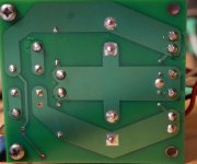
Connect the ground of one amplifier board back to the power supply ground. That is the right hand connections on your third image. The thick middle trace with the connection at the right hand edge of the board.
For testing apply a temporary short circuit across the amplifier audio input. Do not connect to the input sockets yet.
Connect the power supplies for the amp board correctly back to the power board. Be certain to get polarity correct.
Connect the speaker socket ground terminal back to the power board centre trace but connect it to the left of the other ground terminals. Scrape some of the green coating off and solder to that.
Connect the positive speaker output socket to the amplifier board.
Switch on and check the DC voltage across the speaker terminal is zero.
Now try a speaker. It should all be quiet.
I would strongly advise you use DBT (dim bulb tester) for all of this testing.
Thanks so much for the grounding advice Mooly! Hopefully I'll get a chance to work on the grounding issues this weekend.
I have one more question before I abandon the possibility of dropping the voltage. Would a drop of 5v via a regulator help, and avoid the major heat and power problems you describe? Maybe with a small heatsink?
One reason I ask is because my main filter capacitors are only rated 50v.
A 5v drop might give me a bit of a safety margin for the chips, and for the capacitors?
The filter caps will actually be fine at up to their rated voltage, the real problem is with the chip and the way it becomes much more prone to failure than when it all runs on lower voltage.
Dropping 5 volts (but that would be per rail... you need a positive and negative regulator remember) would help reliability of the chip but even just a 5 volt drop at say 3 amps is still 15 watts per regulator.
The regulator always goes after the caps... it wouldn't help those. The only way to lower the cap voltage is to use a lower voltage transformer.
Hi Stefan
A good hint i read about a too large voltage for a chipamp is following:
1 use an other transformer...nobody want to spend once again... dont do it...maybe if you build a second amp then it make sense
2 use 3-4 big rectifier diodes to waste about 0,7V-1V for each diode . its not the fine looking idea but it works. so 3 diodes soldered in series wast about 3V at each rail.
chris
A good hint i read about a too large voltage for a chipamp is following:
1 use an other transformer
...nobody want to spend once again... dont do it...maybe if you build a second amp then it make sense2 use 3-4 big rectifier diodes to waste about 0,7V-1V for each diode . its not the fine looking idea but it works. so 3 diodes soldered in series wast about 3V at each rail.
chris
Thanks Mooly! I'll be working on the grounding problems tomorrow, and let you know if I make any progress. I appreciate your patience with me.
chermann-- what spec diodes would you recommend, if I was to give this a try? And at what point in the power supply circuit would I add them?
chermann-- what spec diodes would you recommend, if I was to give this a try? And at what point in the power supply circuit would I add them?
Is it possible to remove some windings from the secondaries of the transformer?
Another option is to add some additional windings in series, connected out of phase.
Diodes will also work. Use general-purpose diodes with a high forward voltage and a current rating of 10 amps or more.
Something else that could work is a capacitor multiplier. There are some designs on DiyAudio.
What do you think is wrong with the grounding?
Hi stefan
As Mark wrote:
Diodes will also work. Use general-purpose diodes with a high forward voltage and a current rating of 10 amps or more.
use them after the rectification or after the decoupling caps. as i see at your first pic (your amp) its not enough space but its important to give the chip less voltage.
chris
Thanks everyone! I tried to tackle the grounding problems, and got the hum down a little. But it still hums a bit, has a slight hiss, and sometimes I think I hear slight clicks in the music while playing at volume. Messes with my mind. Also, the treble, while crystal clear, is accompanied by some background fuzz, if that makes sense.
Maybe I didn't follow the grounding instructions very well? The only change that I made was to pull the speaker grounds from the amp board and solder them to the power supply board, to the left of the amp grounds (as Mooly suggests). I wasn't able to figure out what to do with input grounds from the instructions. Should they tie directly to the house grounding?
Re: using diodes to drop voltage. I'm not inclined to string 10 together, which would give me 7 volts? I would need to do this on both rails-- requiring 20 diodes, which are expensive locally, and even ordering on them on ebay would put me half way to the cost some new boards (which may be damaged anyway).
One more thing-- when I remove the source, I get a hum that increases from quiet when the volume pot is turned all the way down to fairly loud when its turned up. Sounds like 60hz to my ignorant ears.
All this to say, I'm thinking that, what with the grounding questions and the voltage mismatch, I might be better off getting a simple set of ebay boards that match my transformer and go from there.
Here are the options I'm considering-- does anyone have recommendations, or suggest strongly that I should stick with what I have, and get the voltage dropped down, on the hope that these chips weren't damaged?
K851--I can't seem to find much info on these online: 2x Amplifier 100Watt Hi-Fi Digital Class A Stereo Audio Amp Boards K851 | eBay
a yuan-jing board with a bunch of transistors. Is it really class A
Yuan Jing Audio - On-Semi NJW0281/0302/MJE15032/15033 Class-A Mono Power Amplifier Board [50W] - USD $13.40
tda7293, with rectifier on the amp board: TDA7293 85W Audio Amplifier Board AC 12V-33V Mono Single Channel power 2pcs | eBay
mx50se: 2Pcs HiFi MX50 SE 2.0 Dual Channel 100W+100W Stereo Power Amplifier DIY KI X6V5 194452749805 | eBay
Are any of these ideal for my transformer(30-0-30)/rectifier/filter caps (10000ufx2)?
A 2x25v 225VA transformer would be about 45USD, which should be plenty sufficient for LM3875. You could always go a little extra and get 2x25v 300VA for about $60USD, which would give you options later to play with other chips.
With no source attached, short the inputs out and see if the hum goes away. It is probably just picking up the stray 50/60Hz with nothing connected.
Slight clicks when playing at volume might be the protection kicking in seeing you have the amp running at higher than intended voltages. I missed what impedance your speaker are. The protection also kicks in at 4-5 Amps output current from memory. Your speaker impedance will affect this.
DIY Audio is pretty much a 'choose your own adventure'. It all depends on how far down the rabbit hole you want to go.. You can certainly get boards like the MX50 and swap them around and see what works and what you like. Just be aware that some Ebay boards come with crappy components and they may or may not perform well.
I'd personally try to learn as much as I could about this one amp before moving on to others. If you manage to understand the circuit, identify the problem and what the root cause is, it is probably more worthwhile for personal development than just changing boards. I find it more satisfying to solve the problem.
I would spend the $45 on a transformer and see how it performs. Then find a suitable project for the 30-0-30 250VA transformer.
With no source attached, short the inputs out and see if the hum goes away. It is probably just picking up the stray 50/60Hz with nothing connected.
Slight clicks when playing at volume might be the protection kicking in seeing you have the amp running at higher than intended voltages. I missed what impedance your speaker are. The protection also kicks in at 4-5 Amps output current from memory. Your speaker impedance will affect this.
Here are the options I'm considering-- does anyone have recommendations, or suggest strongly that I should stick with what I have, and get the voltage dropped down, on the hope that these chips weren't damaged?
DIY Audio is pretty much a 'choose your own adventure'. It all depends on how far down the rabbit hole you want to go.. You can certainly get boards like the MX50 and swap them around and see what works and what you like. Just be aware that some Ebay boards come with crappy components and they may or may not perform well.
I'd personally try to learn as much as I could about this one amp before moving on to others. If you manage to understand the circuit, identify the problem and what the root cause is, it is probably more worthwhile for personal development than just changing boards. I find it more satisfying to solve the problem.
I would spend the $45 on a transformer and see how it performs. Then find a suitable project for the 30-0-30 250VA transformer.
Last edited:
Thanks for your replies. It's a little daunting, but you might be slowly convincing me to think of this as a learning project, rather than an instant-results project. I also have significant budget restraints, so if I do take this approach, I'll be trying to keep costs down.
Does this transformer look like it might do the trick (with options for input switching/preamp secondaries)? the secondaries sound right, but would the primary windings be simple enough to wire? The description is confusing.
TOROID TECH TOROIDAL POWER TRANSFORMER TC0300-0044 | eBay
Does this transformer look like it might do the trick (with options for input switching/preamp secondaries)? the secondaries sound right, but would the primary windings be simple enough to wire? The description is confusing.
TOROID TECH TOROIDAL POWER TRANSFORMER TC0300-0044 | eBay
The description is a bit confusing... and I think you might possibly struggle with sorting it all out.
If it was a 25-0-25 then the voltages would be higher off load than the 23 mentioned. That is more likely a 20-0-20
The current ratings are vague, how do we know the low voltage winding is only low current.
I would say to many unknowns for a beginner to try and sort out... and ultimately it may not be suitable anyway.
If you look on the first pages of this forum , you can see many used the LM3886 running with +/-50v. It is perfectly safe according to datasheet with +/-42v, and I use it this way. All you need to decrease the Idle +/-45v to 42v is a pair of bleeder resistors , pulling about 150_200ma , that about 270 ohms 10W. As you call it Gainclone to be a replica of Gaincard amplifier, use similarly a sagging supply by reducing the reservoir capacitors to 2200uf.
- Status
- This old topic is closed. If you want to reopen this topic, contact a moderator using the "Report Post" button.
- Home
- Amplifiers
- Chip Amps
- Newbie Gainclone Problems (LM3875)