Thanks so much for the advice everyone! In the end I did buy a new (old) 20v toroid (cheap on ebay-- sorry chermann). Rectified, it gives 28.6 vdc at each rail, no load. And the amp sounds pretty good so far. I do get a turn on/off pop.
Now I'm looking for an enclosure (planning to recycle something), and maybe an input switch. I'll post my progress, and appreciate any further suggestions.
Now I'm looking for an enclosure (planning to recycle something), and maybe an input switch. I'll post my progress, and appreciate any further suggestions.
Attachments
 using a more suitable transformer was definitely the best option.
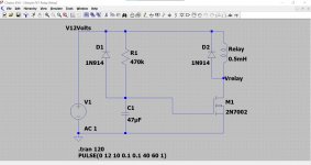
Switch on noises can be hard to eliminate, at least from the basic design. What you need is a simple relay delay to connect/disconnect the speakers.
If you search the usual suspects for 'speaker relay delay' you will see dozens but they don't make it clear whether the power supply needed has to be a separate and floating.
Ideally you want to power it from the supply you have.
You could easily build one from separate parts that would run from your power supply if you wanted to try that. It's little more than a relay and one transistor.
This shows such a design I put together a while ago. Easy to change for your power supply.
Attachments
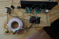
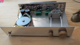
Thanks again for your suggestions. I've made some progress on the project (and several mistakes) and would appreciate your input at this stage. I think I've got the power side of the amp finished, with the input/output side waiting on some parts. I decided to leave the turn-on relay for another time, and just build something basic for now.
Does anything stand out as especially problematic on the power side of this amplifier. Or the grounding? You can't tell from these pictures, but the ground from the three prong AC plug is wired to the ground screw that you see with a thick solid-core copper wire, like the one that connects my power board to that screw. Speaker outputs will be grounded to the bottom of my power board (as Mooly suggests) and input grounds will be floating. Is this a sensible setup for a beginner?
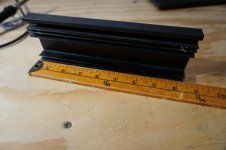
Also, does my heatsink setup look sufficient? I'm planning to mount the heatsink in the picture to the aluminum enclosure with 4 screws (plus the 2 machine screws for the chips), with a 1mm layer of silicon thermal pad.
Lastly, I bought a silver plated input switch (C&K). I've since learned that gold is the usual choice. Does anyone have experience with silver plated switches for inputs? Is it even worth getting it soldered in, or will it just not work for these low-level signals?
Does anything stand out as especially problematic on the power side of this amplifier. Or the grounding? You can't tell from these pictures, but the ground from the three prong AC plug is wired to the ground screw that you see with a thick solid-core copper wire, like the one that connects my power board to that screw. Speaker outputs will be grounded to the bottom of my power board (as Mooly suggests) and input grounds will be floating. Is this a sensible setup for a beginner?
Also, does my heatsink setup look sufficient? I'm planning to mount the heatsink in the picture to the aluminum enclosure with 4 screws (plus the 2 machine screws for the chips), with a 1mm layer of silicon thermal pad.
Lastly, I bought a silver plated input switch (C&K). I've since learned that gold is the usual choice. Does anyone have experience with silver plated switches for inputs? Is it even worth getting it soldered in, or will it just not work for these low-level signals?
Attachments
The input grounds don't actually 'float', they still have electrical continuity to the amplifiers ground connection but it is the routing of how everything connects that is important.
Although having electrical continuity, the actual input socket grounds should be insulated from the metal chassis... is that what you mean")
Have a look at the image in post #38 here:
3 stage LIN topology - NFB tappings?
And also post #45:
3 stage LIN topology - NFB tappings?
Although having electrical continuity, the actual input socket grounds should be insulated from the metal chassis... is that what you mean
Have a look at the image in post #38 here:
3 stage LIN topology - NFB tappings?
And also post #45:
3 stage LIN topology - NFB tappings?
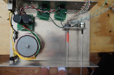
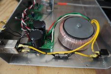
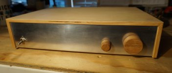
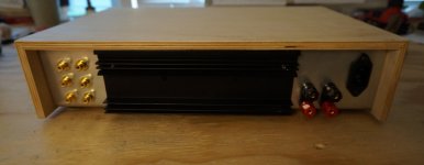
Thanks again everyone (Mooly especially) for your input. I don't think I would have had much success without this forum. I thought I'd post a few pictures in case anyone was interested where this project wound up. The amp sounds great! No hiss/hum/etc., just clean, punchy sound.
I'll mention two things I learned that might be helpful for others: the thermal pads are great-- only a 10 degree (F) difference between the chip on the inside of the enclosure and the heatsink fins on the outside.
The silver plated C&K switch sounds fine to my ears so far. We'll see how it holds up.
I'd do a number of things differently if I did it again, which I might, with my extra toroid.
I'll mention two things I learned that might be helpful for others: the thermal pads are great-- only a 10 degree (F) difference between the chip on the inside of the enclosure and the heatsink fins on the outside.
The silver plated C&K switch sounds fine to my ears so far. We'll see how it holds up.
I'd do a number of things differently if I did it again, which I might, with my extra toroid
.Attachments
Well that's looking great stefan I'm pleased it all came good in the end
Thanks for the kind words
I'm pleased it all came good in the end Mooly should get a medal or something, he is helpful in large number of threads, much harder to crack than this...
Thanks for the kind words
Thanks again everyone (Mooly especially) for your input. I don't think I would have had much success without this forum. I thought I'd post a few pictures in case anyone was interested where this project wound up. The amp sounds great! No hiss/hum/etc., just clean, punchy sound.
I'll mention two things I learned that might be helpful for others: the thermal pads are great-- only a 10 degree (F) difference between the chip on the inside of the enclosure and the heatsink fins on the outside.
The silver plated C&K switch sounds fine to my ears so far. We'll see how it holds up.
I'd do a number of things differently if I did it again, which I might, with my extra toroid
Nice amp Stefan - congratulation !!
Chirs
Hello everyone!
Please, where can I buy these two Gainclone (LM3875) amplifiers? Or, if they are not exactly the same, where will I find something similar?
Thanks.
Audiosector still sells LM3875 kits but as Mooly mentioned, there are plenty LM3886 options.
LM3875 Kit – Audiosector
- Status
- This old topic is closed. If you want to reopen this topic, contact a moderator using the "Report Post" button.
- Home
- Amplifiers
- Chip Amps
- Newbie Gainclone Problems (LM3875)