I just finished building an LM3886 chip amp with the amp boards from circuitbasics.com and Mark Johnson’s PSU board. I thought the amp was fine when I first tested it on my inefficient Minimus 7 test speakers, but when I hooked it up to VERY efficient Cornwall’s I noticed a lot of what I think is ground noise (crunching, whirring, and some radio frequencies) and its pretty loud. I first confirmed 0mv DC offset.
Since I didn’t have the PSU from circuitbasics.com, I thought that I could create a “ground hub” from a plastic terminal block by splitting the ground. The PSU ground, signal ground, speaker ground, and PCB ground all connect to this and I am now realizing this is NOT a good grounding scheme.
I currently have two rca inputs that go into a switch for input 1/2 and then into an Alps Blue pot which has the ground tabs connected and a wire connecting to the ground hub. I did upgrade my wires to shielded cable which helped.
Hoping to get some help on this as i have read multiple forums and looked at a lot of pics and I can’t find a similar wiring to mine.
Thanks!
Attachments
You'll need this. Would not recommend the twist-on connector, though.
Is there a connection to the chassis?
http://hifisonix.com/wordpress/wp-content/uploads/2019/02/Ground-Loops.pdf
Is there a connection to the chassis?
http://hifisonix.com/wordpress/wp-content/uploads/2019/02/Ground-Loops.pdf
Last edited:
Yes. That connector is temporary and I plan to replace.
There are three wire points where I grounded to the chassis. One is from the IEC to star ground and a wire from the star ground goes to the PSU board “star.”
The other I connected the ground tabs together on my rcas and connected to the chassis. After reading more I for sure need to remove this one.
What I have seen from other builds and reading is one star ground that connects all grounding points (rca ground, speaker return, PSU ground, star ground, and each amp board ground).
I hope this is a step in the right direction.
Connect the IEC ground directly to the chassis next to the IEC socket, with a short wire
of the same thickness as the ones in the line cord. Nothing else should connect there.
The RCA grounds must float from the chassis and go to the audio ground.
Otherwise read the document, it is very well done.
of the same thickness as the ones in the line cord. Nothing else should connect there.
The RCA grounds must float from the chassis and go to the audio ground.
Otherwise read the document, it is very well done.
Last edited:
the amp boards I’m using don’t have an rca -in as the circuitbasics tutorial shows to
wire them directly to the PSU ground.
Nope, the input RCA grounds go to the audio ground, often through a loop breaking resistor.
See the document.
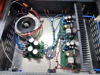
Mark, I just decided to remove the selector switch and volume knob and just build it as a power amp. I moved the transformer to the front left, PSU to the middle, and mounted the amp boards a bit different than you asked (run perpendicular with back of chassis).
I have one amp board hooked up now. It helped some, but I am still getting noise. Mainly radio frequency and and some hum/hiss. If I zip tie ALL my ground wires that meet up, the sound almost disappears completely but I understand I am supposed to separate these wires.
I have one amp board hooked up now. It helped some, but I am still getting noise. Mainly radio frequency and and some hum/hiss. If I zip tie ALL my ground wires that meet up, the sound almost disappears completely but I understand I am supposed to separate these wires.
Chip Amp Photo Gallery
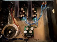
Here you can see how it should look like. Minimal wiring and the sinks act as shielding. Look to install HBR and GLB as shown in the earlier posted link.
Here you can see how it should look like. Minimal wiring and the sinks act as shielding. Look to install HBR and GLB as shown in the earlier posted link.
I added the Ground Loop Breaker and 1NF ceramic across the rca ground and chassis.
It seems it took care of some noise but I noticed I am mostly picking up radio frequencies now. If I move around my speaker and power cables I can eliminate the radio channel but it seems like the speaker cables are acting as antennas and there is still some buzzing.
Any ideas on what to try next?
It seems it took care of some noise but I noticed I am mostly picking up radio frequencies now. If I move around my speaker and power cables I can eliminate the radio channel but it seems like the speaker cables are acting as antennas and there is still some buzzing.
Any ideas on what to try next?
Attachments
I'm no expert, only a hobbyist at this, but some things I would investigate:
1. There is a long yellow wire extending from the power supply filter PCB to the safety ground connection. If that wire is supposed to connect the filter PCB ground to the chassis, can it be shorter and connect to the mounting plate right at the power supply filter PCB?
2. There are long grey wires that appear to come from the audio input jacks. If those are the audio input feed to the amp boards, make them much shorter and use as direct path as possible from the input jacks to the amp audio input connections.
3. There appear to be a couple of black wires extending into the air from the filter PCB. Is there a reason those are there?
4. Does the radio interference go away or lessen when the case is closed up and screwed together?
5. The speaker wires and DC feed wires to the amp boards are intermingled. Is it possible to separate them?
Overall, make all connections only as long as they need to be to get from their start to their finish (don't make them taught though).
This is what I would do:
Place a 1R resistor and 2 diodes back to back (HBR) between C4 and C6 on the underside of the amp boards.
Connect the speaker return/ground to C6 topside.
Connect the power 0V/ground in a Y between the two amps and PSU.
Place a GLB between chassis and Power 0V/ground. Use a 10R >5W resistor and 35A Bridge Rectifier.
Connect the PE to chassis.
I think you missed installing the Thiele Networks at speaker terminals. Thiele network reduces oscillations caused by capacitive loads, usually due to long speaker cables. It also prevents radio frequencies picked up by the speaker wires from getting back into the amplifier’s inverting input through the feedback loop.
- Status
- This old topic is closed. If you want to reopen this topic, contact a moderator using the "Report Post" button.
- Home
- Amplifiers
- Chip Amps
- Grounding help Circuitbasic LM3886 and Mark Johnson PSU