I'm trying to fix a Renkforce E-SA9 that is noisy on one channel. I know the amp is crap and worthless but I'm determined to fix it.
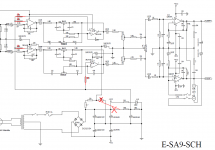
The right channel works fine but the left channel is noisy. The source signal can be heard but is drowned in hissing white noise (no popping or crackling). This is the only schematic I can find for the amp (attached below): Renkforce E-SA9 Stereo amplifier 2 x 12 W Silver (metallic), Dark brown | Conrad.com It's not quite accurate since some of the caps are electrolytics on the schematic but on the actual board are surface mounted non-electrolytics. Some other electrolytic values are different.
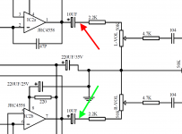
I'm using a signal generator app on a tablet to send tones. Probing around with an earpiece I can hear the noisy signal on the output cap of IC2a pin 1 (red arrow below). There is no noise on the same cap on the right channel (green arrow) which uses the other opamp in the dual package.
I've replaced both JRC4458 dual opamps and the red arrowed 10uF SMT cap. I've lifted the supply pins 3 and 5 of the output LM1875 in case the noise was coming from the output amps. The noise is still there.
Any ideas what might be causing it, what might be worth changing?
many thanks
The right channel works fine but the left channel is noisy. The source signal can be heard but is drowned in hissing white noise (no popping or crackling). This is the only schematic I can find for the amp (attached below): Renkforce E-SA9 Stereo amplifier 2 x 12 W Silver (metallic), Dark brown | Conrad.com It's not quite accurate since some of the caps are electrolytics on the schematic but on the actual board are surface mounted non-electrolytics. Some other electrolytic values are different.
I'm using a signal generator app on a tablet to send tones. Probing around with an earpiece I can hear the noisy signal on the output cap of IC2a pin 1 (red arrow below). There is no noise on the same cap on the right channel (green arrow) which uses the other opamp in the dual package.
I've replaced both JRC4458 dual opamps and the red arrowed 10uF SMT cap. I've lifted the supply pins 3 and 5 of the output LM1875 in case the noise was coming from the output amps. The noise is still there.
Any ideas what might be causing it, what might be worth changing?
many thanks
Attachments
Hissing might be ultrasonic oscillation - check the 47pF feedback caps on that channel, check the supply bypass caps are OK. Each opamp needs ceramic decoupling caps though I don't see that in the schematic. Consult JRC4458 datasheet for details.
BTW the 100k resistors on all the non-inverting opamp inputs are contributing to the noise-floor of this device, they ought to be more like 1k. I'd also be tempted to decouple all those non-inverting inputs at the chip so they can't act as antennas for EMI or even unwanted feedback.
BTW the 100k resistors on all the non-inverting opamp inputs are contributing to the noise-floor of this device, they ought to be more like 1k. I'd also be tempted to decouple all those non-inverting inputs at the chip so they can't act as antennas for EMI or even unwanted feedback.
Last edited:
It would take quite a bit to send a 4558 into oscillation.
The choice of 100k there is indeed puzzling. Not sure why they felt the need for any resistors in these spots at all, it's not like a 4558 is a super low noise part with super low input transistor Rbb'. I would suggest trying to eliminate (short) all 4.
What's also puzzling is that opamp +Vs is derived via a 335R/430R voltage divider from Vcc, but Vref = Vcc/2. Why? It's not like you're drowning in voltage headroom to begin with. Probably not the most seasoned designer at work there. I hope they didn't muck up the LM1875 layout too badly.
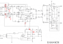
When you are doing the 100k delete, I would suggest taking out the 430 ohm entirely as well, and then reconnecting the 10k/10k divider there (lifting a resistor leg and then running a wire over to where the 430R was should do the trick). Like this:
Actually a bad connection (or resistor) in this leg would also be causing the hiss as observed. Some continuity testing and resistance measurement is in order.BTW the 100k resistors on all the non-inverting opamp inputs are contributing to the noise-floor of this device, they ought to be more like 1k. I'd also be tempted to decouple all those non-inverting inputs at the chip so they can't act as antennas for EMI or even unwanted feedback.
The choice of 100k there is indeed puzzling. Not sure why they felt the need for any resistors in these spots at all, it's not like a 4558 is a super low noise part with super low input transistor Rbb'. I would suggest trying to eliminate (short) all 4.
What's also puzzling is that opamp +Vs is derived via a 335R/430R voltage divider from Vcc, but Vref = Vcc/2. Why? It's not like you're drowning in voltage headroom to begin with. Probably not the most seasoned designer at work there. I hope they didn't muck up the LM1875 layout too badly.
When you are doing the 100k delete, I would suggest taking out the 430 ohm entirely as well, and then reconnecting the 10k/10k divider there (lifting a resistor leg and then running a wire over to where the 430R was should do the trick). Like this:
Attachments
Last edited:
One more tweak that should improve distortion performance and increase input impedance along the way.
The 50k vol / balance pots and the 10k power amp input impedance aren't exactly what I'd call a good match. It all looks like a copypasta hodgepodge really.
The 50k vol / balance pots and the 10k power amp input impedance aren't exactly what I'd call a good match. It all looks like a copypasta hodgepodge really.
Attachments
Last edited:
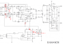
OK, so maybe we should give the Vref generation some protection diodes to safeguard against power up/down gremlins (which may have been why they had these 100k resistors in there). Actually I think 1N4148 would be fine, too, or UF4001 Schottkys. Maybe they can be tagged in underneath the board. I think I'd put these in and check whether anything bad happens at all, maybe it actually doesn't. Power-down would be my main worry.
Attachments
Last edited:
Hi! I would suggest bypassing the preamp section completely, it is a very poor design. Remove the vcc/2 resistors and all that stuff. Run the chipamps at 20k/1k gain according to the datasheet. I added a dual volume pot followed by a simple 5532 stereo gain stage, powered by the DUAL psu and a pair of +/-15V regulators. Replaced the faulty 3300uf psu decoupling caps by 4700uf/35v. It's now very quiet. After a few adjustments, I measured 0.028% THD+N @ 1kHz, 20Watts output in a 8ohm load, not that bad. I like this small enclosure ") I use it a lot! cheers
I use it a lot! cheers
I use it a lot! cheersHi folks!
Here's my experience with the Renkforce E-SA9:
My Renkforce E-SA9 was disappointing with an unmistakable, overtone-rich mains hum in the speakers. In addition, a broadband noise could be heard in the right channel, which was superimposed by a quiet rhythmic rattling. Depending on how I routed the speaker cable past the amplifier, the hissing and rattling became louder or quieter. At this moment I couldn't think of using the amplifier with external boxes for a flat screen TV, which is what I actually bought the part for.
So, I decided to open the device and to take a look. You can quickly find a circuit diagram on the Internet. For example here:
https://asset.conrad.com/media10/ad...rker-2-x-12-w-silber-metallic-dunkelbraun.pdf
The hum was not caused by a wiring or layout error, but by the toroidal transformer itself: The transformer comes the preamplifier board much too close and spreads its magnetic field there. This can be remedied by placing some aluminum sheet between the transformer and the preamplifier board. To do this, I used tin snips to cut four small sheets of 1mm pure aluminum. This shields like a 4mm thick sheet of pure aluminum. Since aluminum shields magnetic fields with eddy current losses and this works the better the higher the frequency of the magnetic fields is, the very low-frequency components of the transformer field are hardly shielded, but the higher-frequency components are almost completely shielded. The annoying hum becomes much quieter and appears much less aggressive, so that it is no longer annoying.
The hiss and rattle on the right channel turned out to be HF oscillation. When dismantling the amplifier, it had noticed that the thickly painted upper part of the housing had no electrical contact with the amplifier. This means that it could not function as a shield and therefore the speaker cable could capacitively stray couple back to the amplifier input and cause RF instability.
But that was not the main reason for the instability. The main cause was the 2k7 resistor, which is connected between the inverting inputs of the LM1875 via the "surround" switch. Strictly speaking, it is the long cable that runs across the entire housing to this switch. And at one LM1875 it is even connected directly to the inverting input, which is an absolute no-go in amplifier construction. The inverting input is the most sensitive point of an amplifier. A wire connected to the inverting input acts like an antenna and any capacitively coupled interference into it and injected noise appears highly amplified at the output of the amplifier. The safest way to make an amplifier oscillate.
After I removed all the wiring, including the 2k7 resistor, the hissing and rattling is gone.
Another unpleasant feature of the amplifier is the loud power-up pop. Although the power amplifiers receive a symmetrical power supply, the preamplifiers - for completely inexplicable reasons - unfortunately only receive an unbalanced one. And since the electrolytic capacitors in the signal path first have to charge themselves to around 10V when the amplifier is turned on, this results in a very loud switch-on pop, almost a bang. A conversion to a symmetrical power supply would be possible, but (since I need the tone control) this would require much deeper changes in the circuit. At this moment the only remedy is to turn the volume down to zero before switching on.
Kai
- Home
- Amplifiers
- Chip Amps
- Renkforce E-SA9 noisy on one channel