Hello everybody, I just joined this wonderful community ")
I have a little PAM8403 amplifier, that looks like this:
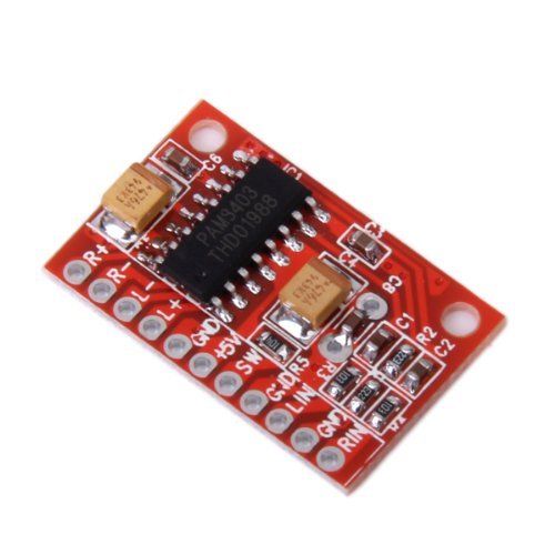
and I was wondering if it would work to build a simple headphone amplifier for an electric bass guitar (my inspiration is the Vox amPlug headphone amp). Does anybody have any experience in this direction?
Thank you!
I have a little PAM8403 amplifier, that looks like this:
and I was wondering if it would work to build a simple headphone amplifier for an electric bass guitar (my inspiration is the Vox amPlug headphone amp). Does anybody have any experience in this direction?
Thank you!
Last edited:
Hello everybody, I just joined this wonderful community
I have a little PAM8403 amplifier, that looks like this:
and I was wondering if it would work to build a simple headphone amplifier for an electric bass guitar (my inspiration is the Vox amPlug headphone amp). Does anybody have any experience in this direction?
Thank you!
I haven't tried it but I am convinced it can be done.
BUT, PAM8403 is designed to work in a speaker load. Therefore, give it an 8-10 Ohm (2-5W) load on each output in parallel with the headphone load. Also, the PAM8403 uses no output filter as it relies on the inductance in the speaker cable and the inertia of a speaker membrane.
You only have a very light headphone membrane and a very short headphone cable. After the 8-10 Ohm resistor, connect a 8-10 Ohm resistor (1W) to each output terminal and a 1uF capacitor (preferably foil) between the two other resistor ends. That will form a carrier frequency filter.
If you are interested I can draw a sketch. I have to cook dinner first.

Last edited:
I haven't tried it but I am convinced it can be done.
BUT, PAM8403 is designed to work in a speaker load. Therefore, give it an 8-10 Ohm (2-5W) load on each output in parallel with the headphone load. Also, the PAM8403 uses no output filter as it relies on the inductance in the speaker cable and the inertia of a speaker membrane.
You only have a very light headphone membrane and a very short headphone cable. After the 8-10 Ohm resistor, connect a 8-10 Ohm resistor (1W) to each output terminal and a 1uF capacitor (preferably foil) between the two other resistor ends. That will form a carrier frequency filter.
If you are interested I can draw a sketch. I have to cook dinner first.
Thank you for your answer, FauxFrench! Yes, a sketch would be very much appreciated, thanks! (Of course after you had dinner, bon appetit!)
I also have another question, regarding the volume control. I saw that a simple way to control the volume is to put a potentiometer on the input. But how do I choose the right resistance? I have some 25k pots lying around, would they do the job?
Welcome Francesco
As i hear the first time from this tiny chip i search around here and note some links:
What is this additional capacitor added to PAM8403 Audio Amplifier Board for?
PAM8406 (and PAM8403)
comment here that fit to the pic :
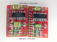
As far as I remember, I had to change the input resistors on my $0.50 PAM boards as well to 47k to get the gain down. 10k is "asian standard". This also brought "noise" down. I use them without permanent supply but with 2x 25F supercaps in series, so having 12.5F with an ESR of ~70mR at 5V.
@FF bon appetit!
chris
As i hear the first time from this tiny chip i search around here and note some links:
What is this additional capacitor added to PAM8403 Audio Amplifier Board for?
PAM8406 (and PAM8403)
comment here that fit to the pic :
As far as I remember, I had to change the input resistors on my $0.50 PAM boards as well to 47k to get the gain down. 10k is "asian standard". This also brought "noise" down. I use them without permanent supply but with 2x 25F supercaps in series, so having 12.5F with an ESR of ~70mR at 5V.
@FF bon appetit!
chris
Attachments
Last edited:
Welcome Francesco
As i hear the first time from this tiny chip i search around here and note some links:
What is this additional capacitor added to PAM8403 Audio Amplifier Board for?
PAM8406 (and PAM8403)
comment here that fit to the pic :
As far as I remember, I had to change the input resistors on my $0.50 PAM boards as well to 47k to get the gain down. 10k is "asian standard". This also brought "noise" down. I use them without permanent supply but with 2x 25F supercaps in series, so having 12.5F with an ESR of ~70mR at 5V.
@FF bon appetit!
chris
Thank you for the links, chermann, they are interesting. So it looks like it's a good idea to add a 470uF capacitor to C7 (or C8), right? Sorry if I ask for confirmation, but I am a newbie of the amp-making art, so I am really not sure about anything right now
.Hi Francesco
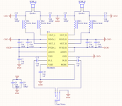
i do not have that chip so i have no experience with it. but yes..you should use your caps....as a look in the datasheet shows the recommendation by the manufacturer pin4 + pin13 PVDD 1x470µF + 2x 1µF for decoupling.
maximum supply voltage 6V!! - so keep around 5V and the chip is ok.
in figure 2 in the datasheet you see that ferrite beads what FF is mentioned.
chris
Last edited:
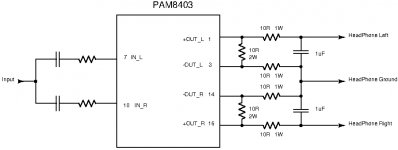
I came to the below circuit. Mono evidently.
The components to the left should already be on the board. The components to the right are added to the board terminals.
I suggest a simple RC output filter because you avoid resonance issues and you have more-than-enough power from a PAM8403 to drive headphones.
The components to the left should already be on the board. The components to the right are added to the board terminals.
I suggest a simple RC output filter because you avoid resonance issues and you have more-than-enough power from a PAM8403 to drive headphones.
Attachments
Thank you for your answer, FauxFrench! Yes, a sketch would be very much appreciated, thanks! (Of course after you had dinner, bon appetit!)
I also have another question, regarding the volume control. I saw that a simple way to control the volume is to put a potentiometer on the input. But how do I choose the right resistance? I have some 25k pots lying around, would they do the job?
I did not find information about input impedance but I am pretty sure that 25K potentiometers will do.
I came to the below circuit. Mono evidently.
The components to the left should already be on the board. The components to the right are added to the board terminals.
I suggest a simple RC output filter because you avoid resonance issues and you have more-than-enough power from a PAM8403 to drive headphones.
Thank you very much for the sketch! Could I please ask you, if you have time, to explain me how you came up with those values of resistance and capacitance?
Hi Francesco
i do not have that chip so i have no experience with it. but yes..you should use your caps....as a look in the datasheet shows the recommendation by the manufacturer pin4 + pin13 PVDD 1x470µF + 2x 1µF for decoupling.
maximum supply voltage 6V!! - so keep around 5V and the chip is ok.
in figure 2 in the datasheet you see that ferrite beads what FF is mentioned.
chris
Thanks! There's just something that I don't understand. On the datasheet I can indeed see that there's a 470µF cap connected to pin4 and pin13, but how do I know that those pins correspond to C7 on the board?
And for what concerns the ferrite beads, yes, indeed it is even suggested in the datasheet:

So, the question now is: how the method with ferrite beads compare with the RC output filter suggested by @FauxFrench?
Again, thanks everyone for the precious advice!
Hi Francesco
its not needed to ask in 2 different threads...you will get answer
C7...
the only change is to check the layout pcb is according to the datasheet. turn around the board and look at the lines and check pin per pin where it goes--> "reverse engineering"
the Class D chip is working with its internal PWM modulation (300kHz - 600khz) -"working" frequency. this modulates the input signal - this gets amplified - and then it must be filtered out because of EMI - electromagnetic interference (RFI)to other devices!
Electromagnetic interference - Wikipedia
this filtering is done by a inductance and a cap - the ferrite beads are very small inductance which can handle very small currents.
chris
Attachments
Probably doesnt have a high enough input impedance for a passive guitar. And its 5 watts into 4 ohms it will be a lot less into high impedance headphones.
You are right that it will be much less than 5W in high impedance headphones.
Without knowing much about headphones, 200mW in 32 Ohm should be quite decent. 200mW in 32 Ohm requires a voltage of 2.5Vrms which is possible because the PAM8403 has a BTL-coupled output.
There *really* are better chips for headphone amps. You do not need class D for a milli-Watt job. You do NOT want bridge-mode output for common 3-wire headphones.
I fully agree it is not an obvious or rational choice. The initial question from the OP was if it "would work" and my impression is that it is possible to make it work.
Sometimes you have such items lying around and like experimenting with their use. As a commercial product it is no good.
Last edited:
I fully agree it is not an obvious or rational choice. The initial question from the OP was if it "would work" and my impression is that it is possible to make it work.
Sometimes you have such items lying around and like experimenting with their use. As a commercial product it is no good.
Yes, that's exactly my situation. I found this little thing in a drawer (I don't even remember how/when I got it), and I thought I might try to build an headphone amp for my bass, since I don't have one (and since I am quarantined...). I could, of course, buy a better chip, but I think it would be fun to see what can come up with this one.
Unfortunately, I cannot really start right now, because I realised I am missing other pieces (the 470uF cap, and the female audio jack for connecting the earphones)... So for the moment, I am just gathering information.
For the headphones, I will be using Sennheiser HD 205, which have 32 Ohm impendance.
Could you guys/girls please elaborate on this statements? I don't really understand what you are talking about...
PRR said:You do NOT want bridge-mode output for common 3-wire headphones.
cbdb said:its 5 watts into 4 ohms it will be a lot less into high impedance headphones.
FauxFrench said:200mW in 32 Ohm should be quite decent. 200mW in 32 Ohm requires a voltage of 2.5Vrms which is possible because the PAM8403 has a BTL-coupled output.
Hi Francesco.
i try point 2 and 3:
electrical power is the product of power P = Voltage U * current I => P=U*I
if you but in ohms law , U=I*R then you will get P= U^2/R or P= I^2 *R.
so the resistor = speakers impedance = headphones impedance , yours 32ohm at the same level of output voltage limit the current and therefore the electrical power. but as FF wrote enough for headphones.
P = U^2/ R = (2,5Vrms ^2 )/ 32R = 0,195Watt or 195mWatt
if you would use a 16ohm headphone- less resistance more current
P = U^2/ R = (2,5Vrms ^2 )/ 16R = 0,390Watt or 390mWatt
for point 1 by PRR i am not sure what he mean....but he will give us an answer
chris
Last edited:
- Status
- This old topic is closed. If you want to reopen this topic, contact a moderator using the "Report Post" button.
- Home
- Amplifiers
- Chip Amps
- Electric bass headphone amp with PAM8403