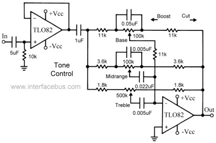
I'm designing a power amplifier with tone controls to be fed with the output of RIAA preamped MM cartridge signal. The signal level after the RIAA preamp is about 500mv and the 3-band tone controls can either cut or boost the treble, the mid and the bass. Upon boosting, it can give out about 2.6v @ 20Hz, so, can the STK459 handle such voltage? This circuit I intend to use is based on the above figure with the NE5532 instead of the TLO32:
So, what you're sayiung is that the STK can't handle 2.6v?If you use volume pot after phono preamp and before tone control (this diagram) there will be no problems with input signal to STK.
probably not.So, what you're sayiung is that the STK can't handle 2.6v?
But in any case, read-the-datasheet

What is the input sensitivity they quote to reach rated power?
Any higher signal will send it into clipping.
Insert a volume control between preamp and tone control + power amp .
Like on any Hi Fi amplifier.
I do plan to have a volume knob in between.
I've read, but it doesn't say anything about input sensitivity.[
But in any case, read-the-datasheet
STK459 pdf, STK459 description, STK459 datasheets, STK459 view ::: ALLDATASHEET :::
^^^^^^ that.
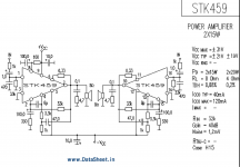
That said, the datasheet you linked is a poor scan and the bottom of the page is chopped, so amp NFB values are missing.
But I found this:
Gain is (33k/1k)+1 so 34 X.
Using Rayma´s Math:
STK459 power: 15W RMS into 8 ohm load so Vout=11V RMS
Sensitivity=11V/34=320mV RMS
So even 500mV straight from your preamp will make it clip ... IF you set volume pot to 10 that is.
But in normal use, you will set volume to whatever is needed, not more.
Attachments
Last edited:
Thanks for the adivices, I'll make sure to add a volume pot in order to set the maximum input 300mV as the maximum input voltage into the STK. Considering that if the 3 pots are in the mid point, I'll have a flat response of 0dB for the audio spectrum, wouldn't it be better redesign such circuit in a way it won't boost, just cut? I'm talking about replacing the bass and midrange pots by a 47k or 51k resistor in series with a 50k pot and do the same with the 500k pot, substituting it by a 250k pot and a 240k or 270 resistor.
That is correct. Another FET input part would be a better match. (If TL072 is too wimpy, maybe OPA1642?)If you use a bipolar opamp in that tone section then the base pot may give issues as you are passing the opamp bias current through its wiper.
Besides, I would use this relatively noisy tone circuit at line level only, with the volume pot following. I would use maybe a 20k volume pot and another opamp to provide anywhere from unity gain to +6 dB.
Actually the 5532 should work well for that position then, levels at this point are low (so common-mode distortion should be a non-issue) and you would have no problem getting feedback network impedance low enough, e.g. 1k/1k, as the part is a good load driver. (It would need an input capacitor of maybe 10 µF and a ca. 47 kOhm bias resistor to ground though; I would also add 220-330 ohms in series with the noninverting input for stability reasons.)
I found another version of the sample circuit, the disappearing resistor is a 330 ohm there, so Av = 40 dB. Output noise is given as 1.2 mV, which is rather unacceptably high in my book. (The STK4xxx2II series has the same spec, it's a maximum there. Not very meaningful.) I did not find a spec for minimum stable gain, but knowing these old circuits, it may not be lower than 30-34 dB.
FWIW, I turned up an amplifier using the larger STK-461 (2x20 W), the Akai AM-U01, with schematic and specs. It uses almost exactly the application circuit and is given with an SNR spec of 90 dB. That would be ca. 400 µV of output noise, rather more in line with a (run of the mill) 1980 vintage hi-fi amplifier and indicating ca. 4 µV worth of effective input noise.
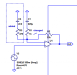
You know what? I would want to use a bit of a trick to bring gain on the STK down:
I think we can live with a boost of +0.2 dB at 10 kHz and +0.7 dB at 20 kHz.
Then the preceding opamp (5532) could be set up for a voltage gain of ca. +6.6 dB (for example, 1.2k + 1k) to make up for the lost gain. Most of it, anyway - a 15 wpc amp does not really need more than 37 dB of gain even for a 150 mV input sensitivity.
All of this would drop output noise from ca. 400 µV to 150 µV, far more in line with a decent amplifier. (The bottleneck is in fact still the STK...)
Note: The 6 MHz GBW assumed in simulation for the amplifier model is likely to be overly conservative. It is likely to be anywhere from 10 to 100 MHz in reality, possibly 20-30. An LM1875 (typical gain +26 dB) is spec'd with 5.5 MHz already.
Attachments
Last edited:
That is correct. Another FET input part would be a better match. (If TL072 is too wimpy, maybe OPA1642?)
Besides, I would use this relatively noisy tone circuit at line level only, with the volume pot following. I would use maybe a 20k volume pot and another opamp to provide anywhere from unity gain to +6 dB.
Actually the 5532 should work well for that position then, levels at this point are low (so common-mode distortion should be a non-issue) and you would have no problem getting feedback network impedance low enough, e.g. 1k/1k, as the part is a good load driver. (It would need an input capacitor of maybe 10 µF and a ca. 47 kOhm bias resistor to ground though; I would also add 220-330 ohms in series with the noninverting input for stability reasons.)
I found another version of the sample circuit, the disappearing resistor is a 330 ohm there, so Av = 40 dB. Output noise is given as 1.2 mV, which is rather unacceptably high in my book. (The STK4xxx2II series has the same spec, it's a maximum there. Not very meaningful.) I did not find a spec for minimum stable gain, but knowing these old circuits, it may not be lower than 30-34 dB.
FWIW, I turned up an amplifier using the larger STK-461 (2x20 W), the Akai AM-U01, with schematic and specs. It uses almost exactly the application circuit and is given with an SNR spec of 90 dB. That would be ca. 400 µV of output noise, rather more in line with a (run of the mill) 1980 vintage hi-fi amplifier and indicating ca. 4 µV worth of effective input noise.
You know what? I would want to use a bit of a trick to bring gain on the STK down:

I think we can live with a boost of +0.2 dB at 10 kHz and +0.7 dB at 20 kHz.
Then the preceding opamp (5532) could be set up for a voltage gain of ca. +6.6 dB (for example, 1.2k + 1k) to make up for the lost gain. Most of it, anyway - a 15 wpc amp does not really need more than 37 dB of gain even for a 150 mV input sensitivity.
All of this would drop output noise from ca. 400 µV to 150 µV, far more in line with a decent amplifier. (The bottleneck is in fact still the STK...)
Note: The 6 MHz GBW assumed in simulation for the amplifier model is likely to be overly conservative. It is likely to be anywhere from 10 to 100 MHz in reality, possibly 20-30. An LM1875 (typical gain +26 dB) is spec'd with 5.5 MHz already.
Do you think +-2dB at each potentiometer would be enough for a cut and boost of the baas frequencies, the mid and the trebles? I came to this value in order to have a 56% of the maximum STK power as the pots are in the midle, and 88% of the maximum power at low frequencies, if the bass pot is at the maximum boost position and so on for the other 2 pots.
That's not a lot. Usually you get somewhere around 10 dB. Maybe 8 dB, but certainly more than 2.Do you think +-2dB at each potentiometer would be enough for a cut and boost of the baas frequencies, the mid and the trebles?
The question is how much use there is left for old-fashioned tone controls in an age where people are increasingly using measurement microphones and MiniDSPs or similar.
Can you please explain me why your sugested circuit would reduce the noise? And also, I thought of +-2dB at each potentiometer in order to not esceed the maximum power when one of the pots is spinned all the way to the boost direction. I though of using a voltage divider of 39k/100k, which would give me a signal of about 200mV level. Then, the maximum output voltage considering an average gain of 31dB would be 7.1V applied to a 8ohms load, which means 6.3W. Then, when one of the pots, the bass for exemploe, is all turned all the way on the boost direction, the output power at the low frequencies would be 10w, not exceeding the maximum power of the STK.
Because it reduces STK gain at audio frequencies, allowing higher input levels for better SNR. Even then STK noise still dominates preamp noise, but things should be a great deal more acceptable. Since STK gain is reduced by 6 dB, you would increase preamp gain by 6 dB by turning the first (follower) stage into a noninverting amplifier of gain 2.Can you please explain me why your sugested circuit would reduce the noise?
The rise at ultrasonic frequencies is nothing that a bit of RC (or R/RC) filtering between preamp and power amp couldn't fix. 4.7k + 1 nF (film) looks decent.
You cannot possibly safeguard against the amplifier ever being driven into clipping like that. If it has severe problems under these conditions, a dedicated limiter circuit may be needed.And also, I thought of +-2dB at each potentiometer in order to not esceed the maximum power when one of the pots is spinned all the way to the boost direction.
Last edited:
Because it reduces STK gain at audio frequencies, allowing higher input levels for better SNR. Even then STK noise still dominates preamp noise, but things should be a great deal more acceptable. Since STK gain is reduced by 6 dB, you would increase preamp gain by 6 dB by turning the first (follower) stage into a noninverting amplifier of gain 2.
Right, but how "boost of +0.2 dB at 10 kHz and +0.7 dB at 20 kHz." is better than a flat gain?
You cannot possibly safeguard against the amplifier ever being driven into clipping like that. If it has severe problems under these conditions, a dedicated limiter circuit may be needed.
So, should I think of about +-8dB at each potentiometer and use it carefully to not drive it into clipping?
You are not seeing it then proper way.Right, but how "boost of +0.2 dB at 10 kHz and +0.7 dB at 20 kHz." is better than a flat gain?
So, should I think of about +-8dB at each potentiometer and use it carefully to not drive it into clipping?
Musical amlifiers are not used that way.
The way *everybody* uses an amp is to play some music, rise volume to desired listening volume, which will never be fullpower or even 50% of it, and if necessary set tone controls to whatever you like.
IF amp is used at a sensible listening volume, it will not clip.
IF it does, lower volume accordingly.
Say boosting Bass increased acoustic volume by 6dB, you lower volume pot setting by 6dB and everything stays the same, only bassier (what you wanted).
IF amp clips/distorts regularly, then you need a more powrful one and/or more sensitive speakers.
You are ignoring that Music varies all the time, has dynamic range, and so requires headroom (power reserve) for loud passages.
I see you are under the wrong idea that a recording puts out a constant, invariant level, that the preamp output will be constant 500mV and you base your Math on that.
Well, it does not.
The ONY way a record would put out something similar to that is if it´s a Test record, containing continuous tones at various frequencies, plus some constant volume white and pink noise.
But then *that* is not a "Musical Program" by any means!!!
- Status
- This old topic is closed. If you want to reopen this topic, contact a moderator using the "Report Post" button.
- Home
- Amplifiers
- Chip Amps
- Can the STK459 handle a 2.6v input?