I was thinking about those kits too. I also looked through the Philips semiconductor handbook to see if there are other comparable ICs, with different names. The answer is not really.
It is surprising to me how it is almost always possible to track down 70 year old vacuum tubes, but a 20 year old IC is absolutely unobtainable.
Vacuum tubes still have a market among enthusiasts. Though the volume is limited, I guess the enthusiasts pay good money for the right quality. I know very little about vacuum tubes but my impression is that just by visual inspection you get a good impression if a vacuum tube is a serious product or not.
Elderly chip-amps seem different. There is no strong feeling of enthusiasm for them and the few sold are probably for casual repair. Admitted, newer chip-amps that perform closely as good as a TDA1514A (or even better) exist, they are just not pin compatible. I am certain that somewhere there are spare stocks of TDA1514, I just don't know where and the numbers are probably limited. Visual inspection of ICs is of no use and the ones I bought for a modest price at least look very Philips-like. Inside, they are hardly even discarded TDA1514 production as my specimens did not behave like TDA1514 in any datasheet sense. They appear to be plain scam-products.
These ICs did not cost me much, the test-board was quick to assemble and I can tell other forum members about my findings. They served a purpose after all though not what I hoped. I am pleased, as Turbowatch2 writes, that I did not start constructing a serious amplifier and late in the project realized that my TDA1514 ICs were useless.
A treasure hunt for the last genuine TDA1514 is hardly worth the effort and those easy to buy are most likely nothing but poor fire-crackers. Let's keep the good reputation in the past of genuine TDA1514 in our minds and let the fakes remain with a few Asian shops.
I know very little about vacuum tubes but my impression is that just by visual inspection you get a good impression if a vacuum tube is a serious product or not.
No, not necessarily so. Decades ago I bought some KT88's that were made by the Shuguang factory. They looked very similarly to the G.E.C. ancestors, but eventually turned out to be exactly the firecrackers Chinese tubes were/are famous for.
Best regards!
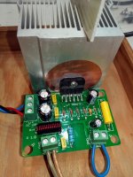
Yesterday I connected a cheap, but quite well made LM3886TF board for a basic test. Price was €8 including P&P from China. Compared to the data sheet the values of the parts are reasonable.
To my surprise nothing bad happened.
Even as my bridge rectifier had a fault and I powered it up with only one rail a few times, it survived. The real LM3886 is supposed to do so.
With input short the open output measures 1mV, which is much less than I expected. A test speaker showed no on/off sound at all. There is a faint hiss if I hold the speaker to my ear.
I can not say anything about sound quality, as I have only one board, but it simply plays music. Maybe I find the time to do some measurements.
So far I can not proof the LM3886TF is fake or real, because of the price I expected a fake chip, but it looks OK.
The 30W power supply is nothing fancy, just a few capacitors with C-L-C filtering, +- 25V DC with amp at idle.
Attachments
Many thanks for the information, Kay. As a boy, I used to take vacuum tubes out of old radios and study the constructions inside. I still have a box of tubes somewhere. Various electrodes, gitters etc...
Today there are still "producers" that can't make 50-60 years old technology work .
.
Today there are still "producers" that can't make 50-60 years old technology work
.Young (no, actually not at all) and naive, I bought a couple of years ago:
* An LM1876 board that worked fine.
* Two cheap TDA7293 boards of which one had a defect TDA7293 chip.
* A TDA7850 board that worked fine.
* TDA 7377 and TDA7388 ICs that worked fine.
* A very cheap TDA7297 board that worked well.
* A very simple TDA2030 board that actually worked.
Luckily it is not always that such purchases are "loosers". It's a gamble what you get and where you sometimes loose. As long as you do not put in much money and can accept loosing.........
Yesterday I connected a cheap, but quite well made LM3886TF board for a basic test. Price was €8 including P&P from China. Compared to the data sheet the values of the parts are reasonable.
....
Hi Turbo
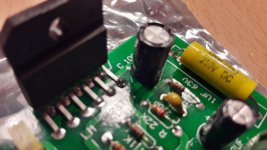
Fine building. funny .... i bought exactly the last board as you 3 weeks ago over a..z..n.11 euro. delivered in 3 days. i claimed the bad soldering (see pics) and the "bad" measurements
") i get the payment refund.
i get the payment refund.pic 1-3 pcb and bad soldering. but it works..
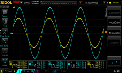
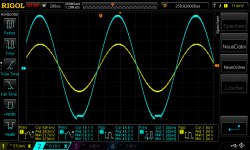
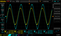
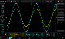
pic 4 25V supply 700mVrms in at 8,2R with 20khz...27,4Watt
pic 5 25V supply 700mVrms in at 8,2R with 80khz
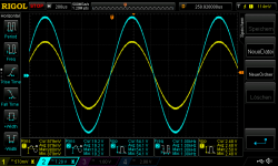
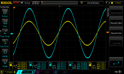
pic 6 25V supply 730mVrms in at 8,2R with 1khz_clipping at negative rail
pic 7 30V supply 860mVrms in at 8,2R with 1khz...45Watt
pic 8 30V supply 860mVrms in at 8,2R with 50khz
no sound check...no updates or changes...looks so far ok for me....
chris
Attachments
-
 30V supply 860mVrms in at 8,2R with 50khz.png52.8 KB · Views: 89
 -
 30V supply 860mVrms in at 8,2R with 1khz.png51.9 KB · Views: 86
 -
 25V supply 730mVrms in at 8,2R with 1khz_clipping at negative rail.png51.3 KB · Views: 85
 -
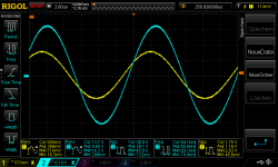 25V supply 700mVrms in at 8,2R with 80khz.png48.6 KB · Views: 64
 -
 25V supply 700mVrms in at 8,2R with 20khz.png50.5 KB · Views: 98
 -
 LM3886 TF board bad solder points_3.jpg112.9 KB · Views: 242
 -
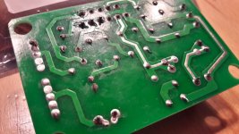 LM3886 TF board bad solder points_2.jpg144.4 KB · Views: 248
 -
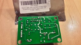 LM3886 TF board bad solder points_1.jpg123.8 KB · Views: 257
@Chris,
Looks fine. Clipping similar to my test board.
yes near the clipping point the amps doing something strange
after a hint by Turbo i ordered this boards 1 month ago...will see:
Free shipping MINI DC12 35V 68W LM3886 Mono Power Amplifier Board (Finished Board) with ERO capacitance|power amplifier board|amplifier board|mono power amplifier board - AliExpress
chris
Yesterday I made a few more tests with my LM3886TF and found a faulty solder joint in my PS. Some of my parts are getting really old, so solder is not always sticking to legs.
Now the amp is 100% silent, even with the tweeter at my ear. The output has .5mV DC hot and cold. If this is the usual offset, I understand why some parallel design ignore servo circuit´s or pot´s.
An .2 Ohm resistor at the outputs should get the multiple chips in line. On the other side, if parallel+bridged, all LM3886 dialed exactly to the same offset should prevent them from interacting with each other and flow no current. The offset being so independent of temperature surprised me.
"My" LM3886TF is immune to shorting the output, one rail missing and over driving it until the 50W transformers voltage breaks down. So far it seems bullet proof.
It flows quite some idle current, as the heat sink gets 38°C warm with +-25V DC. Have to check how much. The negative rail pulls more current, the positive needs much longer to discharge the 13.000 micro F per rail.
The "strange" clipping is the limiter interacting. I do not expect perfect clipping vom any amp that has no separate rails for the driver stages. If I build a domestic 200/400 Watt amp, I will never get it near clipping. So as long as it does not latch up, that is OK. If it was a 15 Watt amp, I would care.
The build quality of this specific, cheap board, is like you expect it. I re-soldered it before even trying it and had some fun removing a short between the chips legs. It was only a "NC" leg to rail V, but it shows how serious our friends in the far east take ignoring quality control.
This board´s layout is not optimized for distance in the feedback loop etc. but works as expected or maybe even a little bit better. I picked it, because it did not have the obvious faults of many other single LM3886 boards on eBay and Aliex.
I did not find the sole PCB or a kit for sale, as it would be nice to build it with serious parts. They sell it only assembled.
The cheap function generator I bought was a close miss, the signals are very distorted, sinus has ripples in it and square signal has wild over shoots. I did not expect it to be so useless.
After a few minutes the low frequency signal output broke down, now I only have the 1-8 MHz output. The software menu still works.
DDS Function Signal Generator Sine Square Triangle Low Frequency X | eBay
Sure, you can not expect HP quality, but something working, like the cheap component tester, that are very handy.
If anyone reading this has one that works, mine might have been all faulty.
But there is something good about it, I found out my made in Germany signal generator from 1980 (!!!) is still made in 2020. So I might get a new transformer, as it has a short in the primary. Probably was still 220V, not 230V type.
@chermann
Chris, you mentioned that the board does something strange.
Before my generator died, I saw something similar to page 9 figure 6 here:
http://www.ti.com/lit/ds/symlink/lm3886.pdf
So your what you call "strange" may be just the advanced protection kicking in.
So it might not be a fault, but a feature! So in my logic, any measure to "correct" this clipping behavior will be useless.
@chermann
Chris, you mentioned that the board does something strange.
Before my generator died, I saw something similar to page 9 figure 6 here:
http://www.ti.com/lit/ds/symlink/lm3886.pdf
So your what you call "strange" may be just the advanced protection kicking in.
So it might not be a fault, but a feature! So in my logic, any measure to "correct" this clipping behavior will be useless.
The strange phenomenom is probably the SPiKe interference in figure 5.
I had it also and as it is intended, Chris can't "iron it out".
Good to see a cheap board that works quite well and can be used for teaching of young DIYers and experiments for experienced DIYers.

test board 3886TF 4,45R load
Hi
just to check the current capability of that chip i try to load with lower resistance to see the current (limiter).
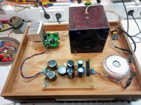
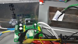
pic 1 test environment
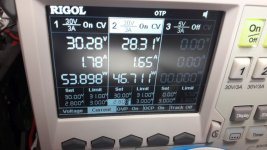
pic 2 power supply at idle
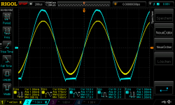
pic 3 30V supply 770mVrms in at 4,459R 1khz about 60Watt --> its 3,8A rms
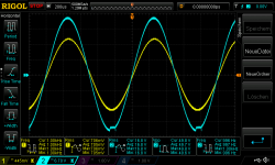
pic 4 30V supply 790mVrms in at 4,459R 1khz clipping negative rail
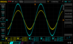
pic 5 30V supply 880mVrms in at 4,459R 1khz clipping both rails
pic 6 30V supply 770mVrms in at 4,459R 20khz about 60Watt
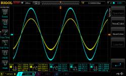
pic 7 30V supply 770mVrms in at 4,459R 70khz about oscillating and SpiKe starts - at this pic i just stop 2 seconds after switch on and the fine sine wave changed and the SpiKe starts...
chris
Hi
just to check the current capability of that chip i try to load with lower resistance to see the current (limiter).
pic 1 test environment
pic 2 power supply at idle
pic 3 30V supply 770mVrms in at 4,459R 1khz about 60Watt --> its 3,8A rms
pic 4 30V supply 790mVrms in at 4,459R 1khz clipping negative rail
pic 5 30V supply 880mVrms in at 4,459R 1khz clipping both rails
pic 6 30V supply 770mVrms in at 4,459R 20khz about 60Watt
pic 7 30V supply 770mVrms in at 4,459R 70khz about oscillating and SpiKe starts - at this pic i just stop 2 seconds after switch on and the fine sine wave changed and the SpiKe starts...
chris
Attachments
-
 30V supply 770mVrms in at 4,459R 70khz about oscillating and SpiKe starts.png59.6 KB · Views: 68
 -
 30V supply 770mVrms in at 4,459R 20khz about 60Watt.png52.6 KB · Views: 62
 -
 30V supply 880mVrms in at 4,459R 1khz clippping both rails.png53 KB · Views: 226
 -
 30V supply 790mVrms in at 4,459R 1khz clipping negative rail.png53 KB · Views: 240
 -
 30V supply 770mVrms in at 4,459R 1khz about 60Watt.png53.4 KB · Views: 237
 -
 LM3886TF test board_idle power 30Vsupply.jpg97.7 KB · Views: 245
 -
 LM3886TF test board.jpg131.8 KB · Views: 254
now with 2,88 R load
here are pic with 2,88R load
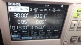
pic 1 30V supply 680mVrms in at 2,88R 1khz about 73Watt..no clipping but the chip immediately get hot!! about 79°C with fan 6cm away !!!
poor boy---current is 14,5Vrms / 2,88R = 5Arms
data sheet is written Io = 11,5A 7A ---> Amin not peak
so a real 3886?
pic 2 shows my power supply. i set it at 2,8A but i do not hit that current limit but the negative rail is always changing from CV to CC mode? i do not reach the current but...whats that?
short cut test not done
chris
here are pic with 2,88R load
pic 1 30V supply 680mVrms in at 2,88R 1khz about 73Watt..no clipping but the chip immediately get hot!! about 79°C with fan 6cm away !!!
poor boy
---current is 14,5Vrms / 2,88R = 5Arms data sheet is written Io = 11,5A 7A ---> Amin not peak
so a real 3886?
pic 2 shows my power supply. i set it at 2,8A but i do not hit that current limit but the negative rail is always changing from CV to CC mode? i do not reach the current but...whats that?
short cut test not done
chris
Attachments
Hi Chris,
5 Arms and 7.1 A peak is a little below what I managed when I got oscillation under control.
The LM3886 current limit is more tricky than 11.5A. The 11.5A is the short-circuit current to ground. The steady-state current limit is around 6A (found in an application note) but it has a dynamic current capability around 9A. Above 9A I had instability.
A very difficult question to answer - fake or genuine? I believe that your cheap LM3886 well demonstrates the performance of a genuine LM3886.
Chris,
you should use a simple, maybe 150-250 VA unregulated PS for your tests. Otherwise you see the protection of your lab supply, not the chip´s.
I´m sure you got some dual 15-25V AC transformer, a bridge rectifier and two 5000uF cap´s or so. Maybe add two slow blow 5A fuses.
IMO you are too much focused on the current limit the chip does or should do in your opinion.
Come down to earth, what does this protection have to do and does it deliver? How often do you permanently clip your amp? How does such clipping sound? (Connect a load resistor to the amp and a speaker in line with a 100 Ohm resistor, parallel, so you can listen to clipping at low volume)
The whole thing shall protect the chip from a short and a failing supply voltage, while allowing huge current peaks, for example around the woofers resonance frequency.
Does it do so? If yes, what is your problem?
When SPIKE is active, there has to be some "strange" wave form at the output.
As the chip does NOT USE complementary output transistors (NPN and PNP), the clipping will not be symmetrical.
See, TI builds chips for OEM not DIYS. No commercial LM3886 amp will have 12A power output. Also the capacitors will be the bare minimum.
So "SPIKE" will not only kick in in an over current situation, but somehow depend on voltage drop, too.
Please, do not try to repair something that is not broken!
If we are lucky, the LM3886TF is real, if not, it must be a very good fake.
Much better than the usual ones, that blow at not even 30V and do not resist to a short at the output.
So the final test would be to run it at 35V and short it...
Anyway, for final conclusion and a serious build do not buy at Conrad, Reichelt eBay or in China, but from someone that is delivered from TI directly and can prove that for any part sold. Try to get such a certificate from Conrad or Reichelt... they buy from the cheapest chip broker that delivers. "We buy from reputable sources (that are a trade secret) and can not keep track for any part we sell" is the usual answer if you complain. You will complain, for sure...
If you take all this serious, your and my LM3886TF are not the right thing to proof anything, as they are from uncertain origin.
If you want to make an honest test, get a real LM3886!
Hi Turbo
hmm.. maybe i was to directly go to the SpiKE or current limiter- but i want to know which chip i have-nevertheless i am happy with that chip. i am really sure its not a real 3386 TF - chip.
sorry ....its my natural to squeezes all out in my hobbies (cycling, ...before RC cars--> national races...etc.)
chris
- Status
- This old topic is closed. If you want to reopen this topic, contact a moderator using the "Report Post" button.
- Home
- Amplifiers
- Chip Amps
- Chip-amps suited as power stage in a composite amplifier, LM1875/TDA2050 excluded.