LM3886
The LM3886 is next in line for an assessment. The minimum gain is stated in the datasheet to be 10 times (20dB).
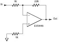
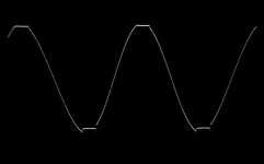
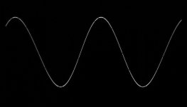
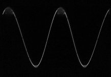
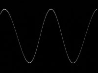
First test was carried out within the recommended gain range using a gain of 22 and an inverting configuration. The supply voltage was +/-26V from a regulated power supply and the load 4 Ohm. For a start, no Zobel-network or Thiele-network was included.
Picture 1: Diagram of the main components.
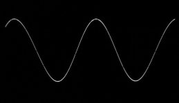
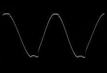
Picture 2: 1KHz sine-wave, 20Vpp.
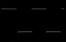
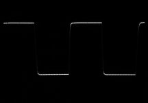
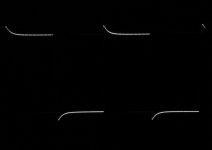
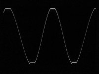
Picture 3: 1KHz square-wave, 20Vpp.
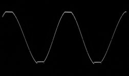
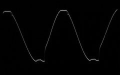
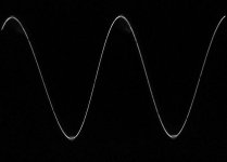
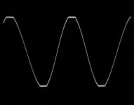
Picture 4: 1KHz sine-wave, clipping at 44Vpp.
Picture 5: 20KHz square-wave, 20Vpp.
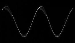
Picture 6: 20KHz sine-wave, clipping at 44Vpp.
The results obtained show a stable amplifier, as expected, only with slightly deform clipping which is best seen from the curve at 20KHz. LM3886 has a “SPiKe” protection system that may be the cause of deformation at clipping. At clipping of the output, the voltage margins to the supply rail voltages were some 3-4V which is reasonable with 4 Ohm loading.
The LM3886 is next in line for an assessment. The minimum gain is stated in the datasheet to be 10 times (20dB).
First test was carried out within the recommended gain range using a gain of 22 and an inverting configuration. The supply voltage was +/-26V from a regulated power supply and the load 4 Ohm. For a start, no Zobel-network or Thiele-network was included.
Picture 1: Diagram of the main components.
Picture 2: 1KHz sine-wave, 20Vpp.
Picture 3: 1KHz square-wave, 20Vpp.
Picture 4: 1KHz sine-wave, clipping at 44Vpp.
Picture 5: 20KHz square-wave, 20Vpp.
Picture 6: 20KHz sine-wave, clipping at 44Vpp.
The results obtained show a stable amplifier, as expected, only with slightly deform clipping which is best seen from the curve at 20KHz. LM3886 has a “SPiKe” protection system that may be the cause of deformation at clipping. At clipping of the output, the voltage margins to the supply rail voltages were some 3-4V which is reasonable with 4 Ohm loading.
Attachments
-
 LM3886Handling.jpg12.6 KB · Views: 411
 -
 LM3886_1KHz_20Vpp_NoZobel.jpg199.7 KB · Views: 389
 -
 LM3886_1KHz_20Vpp_NoZobelSQ.jpg155.5 KB · Views: 381
 -
 LM3886_1KHz_Clip44Vpp_NoZobel.jpg194.7 KB · Views: 383
 -
 LM3886_20KHz_20Vpp_NoZobelSQ.jpg148.1 KB · Views: 393
 -
 LM3886_20KHz_Clip44Vpp_NoZobel.jpg187.9 KB · Views: 86
Last edited:
LM3886
These conclusions are evidently drawn on the LM3886 specimen I had in the test board. If that specimen behaves the same way as other LM3886 specimens, I cannot say.
When the gain was reduced, first to -5 times and subsequently to -3 times (inverting), oscillation on the output signal appeared at higher signal levels, near clipping. The less gain - the more oscillation, just as for TDA7293. For the LM3886, the initial oscillation was less than for the TDA7293 with the same gain.
Initial test with reduced gains, +/-26V supply voltage and 4 Ohm load.
Image 1: Gain -5, 1KHz, amplitude just below clipping level.
Image 2: Gain -3, 1KHz, amplitude just below clipping level.
In order to eliminate the oscillation, I first tried to include a Zobel-network but that only made the oscillation worse. Then, I tried the same CR-string that was used for the TDA7293. Using the same values, 10nF in series with 470 Ohm, immediately removed the oscillation for operation in the linear working area.
A difference between LM3886 and TDA7293, according to my results, is that LM3886 probably is easier to handle in the normal linear working area than the TDA7293 but behaves less predictable when the clipping level is approached.
Most of my efforts trying to optimize the CR-string values and the Zobel-network turned around having a less abrupt behavior when clipping was reached. The values I arrived at may very well vary according to each LM3886 specimen such that the values I chose are somewhat arbitrary.
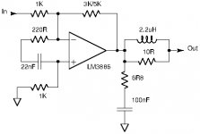
When I had implemented values for the CR-string and Zobel-network, the LM3886 would oscillate permanently with only10nF connected directly at the output. LM3886 certainly requires a Thiele network at the output such as shown in the datasheet. For the Thiele-network I used 2.2uH in parallel with 10 Ohm because that was what I had. The 0,7uH shown in the datasheet should work as well. With the Thiele-network connected directly at the output of the LM3886 IC, the LM3886 would remain stable even when loaded with 1uF.
In the end I implemented LM3886 components as shown in Image 3.
Image 3: Values for the LM3886 peripheral components
In a following posting the output curves at gains of -3 and -5 will be shown.
These conclusions are evidently drawn on the LM3886 specimen I had in the test board. If that specimen behaves the same way as other LM3886 specimens, I cannot say.
When the gain was reduced, first to -5 times and subsequently to -3 times (inverting), oscillation on the output signal appeared at higher signal levels, near clipping. The less gain - the more oscillation, just as for TDA7293. For the LM3886, the initial oscillation was less than for the TDA7293 with the same gain.
Initial test with reduced gains, +/-26V supply voltage and 4 Ohm load.
Image 1: Gain -5, 1KHz, amplitude just below clipping level.
Image 2: Gain -3, 1KHz, amplitude just below clipping level.
In order to eliminate the oscillation, I first tried to include a Zobel-network but that only made the oscillation worse. Then, I tried the same CR-string that was used for the TDA7293. Using the same values, 10nF in series with 470 Ohm, immediately removed the oscillation for operation in the linear working area.
A difference between LM3886 and TDA7293, according to my results, is that LM3886 probably is easier to handle in the normal linear working area than the TDA7293 but behaves less predictable when the clipping level is approached.
Most of my efforts trying to optimize the CR-string values and the Zobel-network turned around having a less abrupt behavior when clipping was reached. The values I arrived at may very well vary according to each LM3886 specimen such that the values I chose are somewhat arbitrary.
When I had implemented values for the CR-string and Zobel-network, the LM3886 would oscillate permanently with only10nF connected directly at the output. LM3886 certainly requires a Thiele network at the output such as shown in the datasheet. For the Thiele-network I used 2.2uH in parallel with 10 Ohm because that was what I had. The 0,7uH shown in the datasheet should work as well. With the Thiele-network connected directly at the output of the LM3886 IC, the LM3886 would remain stable even when loaded with 1uF.
In the end I implemented LM3886 components as shown in Image 3.
Image 3: Values for the LM3886 peripheral components
In a following posting the output curves at gains of -3 and -5 will be shown.
Attachments
LM3886
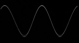
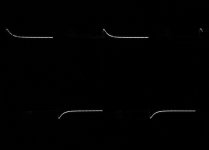
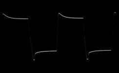
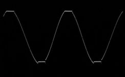
Using the components shown in Picture 3 of posting #22, I obtained the below output curves:
Gain -3 times, +/-26V regulated supply, 4 Ohm load
Image 1: 1KHz sine-wave, 40Vpp amplitude, no capacitive loading.
Image 2: 1KHz sine-wave, clipping at 44Vpp amplitude, no capacitive loading..
Image 3: 20KHz square-wave, 30Vpp amplitude, no capacitive loading.
Image 4: 20KHz sine-wave, clipping at 44Vpp amplitude, no capacitive loading.
Image 5: 10KHz square-wave, 20Vpp amplitude, 100nF capacitive loading after the Thiele-network and signal shown before the Thiele-network.
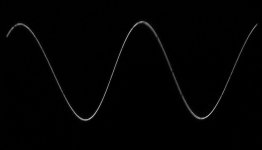
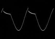
Gain -5 times, +/-26V regulated supply, 4 Ohm load
Image 6: 1KHz sine-wave, 40Vpp amplitude, no capacitive loading.
Image 7: 1KHz sine-wave, clipping at 44Vpp amplitude, no capacitive loading..
Image 8: 20KHz square-wave, 30Vpp amplitude, no capacitive loading.
Image 9: 20KHz sine-wave, clipping at 44Vpp amplitude, no capacitive loading.
Image 10: 10KHz square-wave, 20Vpp amplitude, 100nF capacitive loading after the Thiele-network and signal shown before the Thiele-network.
In a following posting, I will briefly mention if test with my +/-35V LLC power supply resulted in instability. Apart from that, I will terminate my assessment of the LM3886 IC.
Next test object is the UTC-TDA2050V but for the other thread.
Using the components shown in Picture 3 of posting #22, I obtained the below output curves:
Gain -3 times, +/-26V regulated supply, 4 Ohm load
Image 1: 1KHz sine-wave, 40Vpp amplitude, no capacitive loading.
Image 2: 1KHz sine-wave, clipping at 44Vpp amplitude, no capacitive loading..
Image 3: 20KHz square-wave, 30Vpp amplitude, no capacitive loading.
Image 4: 20KHz sine-wave, clipping at 44Vpp amplitude, no capacitive loading.
Image 5: 10KHz square-wave, 20Vpp amplitude, 100nF capacitive loading after the Thiele-network and signal shown before the Thiele-network.
Gain -5 times, +/-26V regulated supply, 4 Ohm load
Image 6: 1KHz sine-wave, 40Vpp amplitude, no capacitive loading.
Image 7: 1KHz sine-wave, clipping at 44Vpp amplitude, no capacitive loading..
Image 8: 20KHz square-wave, 30Vpp amplitude, no capacitive loading.
Image 9: 20KHz sine-wave, clipping at 44Vpp amplitude, no capacitive loading.
Image 10: 10KHz square-wave, 20Vpp amplitude, 100nF capacitive loading after the Thiele-network and signal shown before the Thiele-network.
In a following posting, I will briefly mention if test with my +/-35V LLC power supply resulted in instability. Apart from that, I will terminate my assessment of the LM3886 IC.
Next test object is the UTC-TDA2050V but for the other thread.
Attachments
-
 LM3886_5x_10KHz_20Vpp_100nF_BeforeThiele.jpg244.3 KB · Views: 46
 -
 LM3886_5x_20KHz_Clip44Vpp_NoCap.jpg270.2 KB · Views: 56
 -
 LM3886_5x_20KHz_30Vpp_NoCap.jpg376.2 KB · Views: 48
 -
 LM3886_5x_1KHz_Clip44Vpp_NoCap.jpg292.4 KB · Views: 46
 -
 LM3886_5x_1KHz_40Vpp_NoCap.jpg273.8 KB · Views: 53
 -
 LM3886_3x_10KHz_20Vpp_100nF_BeforeThiele.jpg241 KB · Views: 59
 -
 LM3886_3x_20KHz_Clip44Vpp_NoCap.jpg225.6 KB · Views: 51
 -
 LM3886_3x_20KHz_30Vpp_NoCap.jpg244.9 KB · Views: 48
 -
 LM3886_3x_1KHz_Clip44Vpp_NoCap.jpg259 KB · Views: 49
 -
 LM3886_3x_1KHz_40Vpp_NoCap.jpg288.2 KB · Views: 124
TI: Dual OPA2541 or single OPA541 and OPA549 vanilla/HIREL...?
http://www.ti.com/amplifier-circuit...tml?pqs=paqs&familyid=3523#p233typ=1900;10000
Edit:
OPA548?
http://www.ti.com/amplifier-circuit...tml?pqs=paqs&familyid=3523#p233typ=1900;10000
Edit:
OPA548?
Last edited:
[FONT=FreeSerif, serif]LM3886[/FONT]
[FONT=FreeSerif, serif]I tried the LM3886 test-board with my 500W strong +/-35Vdc LLC power supply. With a 4 Ohm load and the same components as used for the test in posting #23, I turned up the power. At around 28V peak the output would start oscillating, which sometimes led to collapse of the positive half-wave such that the chip drew high currents and the IC had a very high power loss. Two things could improve the situation – either reducing the load to 8 Ohm or increase the gain to 22 (above the minimum gain). I tried lowering the impedance of the CR-string but could not get the chip stable with reasonable values. The board layout and power rail decoupling were such that it would work much better with recommended gain and I accordingly assume that doing a further effort here would bring very little.[/FONT]
[FONT=FreeSerif, serif]Apart from a very well reputed sound in ordinary use, the LM3886 is attractive if the particularly high current limit of 11.5A (typ.) can be used. My immediate impression is that it will be difficult. Either the gain has to be maintained higher than convenient for use in a composite amplifier or, the LM3886 should not be used to near its attractive 11.5A current limit in which case other chip-amps, like the TDA729X series, are serious alternatives.[/FONT]
[FONT=FreeSerif, serif]It has been hinted before that the LM3886 changes dynamic properties with higher supply voltages. It is consistent with that the datasheet only mentions 68W in 4 Ohm as a continuous output power limit. That corresponds to a use of the LM3886 far below the 11.5A current limit. The datasheet also mentions an “Instantaneous Peak Output Power” of 135W. But, relying on such dynamic values in a design is difficult. The specification in the datasheet of 11.5A could actually look like an output short-circuit limit rather than an operational current limit.[/FONT]
[FONT=FreeSerif, serif]For the above reasons, I will terminate testing of the LM3886 and conclude that while it is no doubt a very well sounding chip-amp for ordinary use, it seems not to be what I hoped for when I probably misunderstood the datasheet values.[/FONT]
Could you please test LM3886 one more time, but now use datasheet recommended cap across input pins (220pF, it seems it could be lower, like 180pF ), AND an RC string (~50pF+20k over feedback resistor) simultaneously, thank you!
The LM3886 tends to show a little instability as the output voltage approaches the negative rail. The 180 pF deals with that, but causes overshoot in the transient response. An RC across the feedback resistor usually get things back in line.
TI: Dual OPA2541 or single OPA541 and OPA549 vanilla/HIREL...?
http://www.ti.com/amplifier-circuit...tml?pqs=paqs&familyid=3523#p233typ=1900;10000
Edit:
OPA548?
You are right, the OPA549 is probably what I need though the supply voltage range is a bit limited. I may put OPA549 on my wish-list for Christmas. The price is even affordable.
Why do I bother with ordinary audio chip-amps? Because I have the same naive hope as alchemists and people digging for gold on Dovre Fjellet. The illusion to get a lot for very little. At least the "fake" LM1875 I had could work down to a gain of -3 without further effort. I hope that the UTC-TDA2050 has similar qualities. The UTC-TDA2050 costs 1 Eur per piece (around 100 NKR now-a-days) and can be bought in small quantities with a moderate shipping fee.
But, I should invest more and get the right thing for a start.
Thanks for the KaffiMann home-page link. Good music (New Age genre?). Now I know how it looks when a proud Norwegian listens to the grass grow and what are the minimum standards (lucky them) for a teenage stereo in Norway. Hope you got a good price selling your house not so long ago.
You're steamrolling through this!
Will you really test all the amplifiers on the list in the other thread? This is an incredible contribution to the forum!
Some people collect Rolex watches, other fancy sports-cars. I collect outdated class AB chip-amps because that is within my budget
 . Honestly, I have bought them at very attractive prices and I am curious to know how they actually perform (to get the "feeling"). I have all those in the scheme I drafted around a month ago and some more that are not suited for a composite amplifier. I will slowly try them all. For learning that remains in my head, I need to do "hands on".
After my self-retirement I should spend my time playing bridge and watch television. Doing DIY electronics is a way to refuse admitting that I am getting old and should be doing useless activities.
Could you please test LM3886 one more time, but now use datasheet recommended cap across input pins (220pF, it seems it could be lower, like 180pF ), AND an RC string (~50pF+20k over feedback resistor) simultaneously, thank you!
Will do, tomorrow. Dinner's ready!
This is great, FauxFrench! That's a pretty aggressive noise gain compensation network if I'm looking at it right, but seems to be working. Did you perchance have a look at the -3db point in your 3886, to corroborate that with the 7293. We might gain some insight into how to shape a composite loop around these parts more optimally.
Hopefully we can drag JCX into the discussion... he's the wiz with crazy gain structures.
*I have a few 7293's that I liberated from a computer speaker setup donated to me where the control board died, and I should probably put them to use at some point.
Hopefully we can drag JCX into the discussion... he's the wiz with crazy gain structures.
*I have a few 7293's that I liberated from a computer speaker setup donated to me where the control board died, and I should probably put them to use at some point.
Last edited:
Thanks for the KaffiMann home-page link. Good music (New Age genre?). Now I know how it looks when a proud Norwegian listens to the grass grow and what are the minimum standards (lucky them) for a teenage stereo in Norway. Hope you got a good price selling your house not so long ago.
Thank you for the nice words.
The link is just in my sig line, there's a new album release beginning of april, proper album release. Got signed.
The new music is much better than that old thing, saved the good stuff for the right moment.
Kids are making noise and all is well.
Looking forward to numbers on the OPA549.
This is great, FauxFrench! That's a pretty aggressive noise gain compensation network if I'm looking at it right, but seems to be working. Did you perchance have a look at the -3db point in your 3886, to corroborate that with the 7293. We might gain some insight into how to shape a composite loop around these parts more optimally.
Hopefully we can drag JCX into the discussion... he's the wiz with crazy gain structures.
*I have a few 7293's that I liberated from a computer speaker setup donated to me where the control board died, and I should probably put them to use at some point.
-3dB bandwidth of TDA7293 with 4Vpp amplitude was close to 600KHz.
-3db bandwidth of LM3886 with 4Vpp amplitude was close to 400KHz.
Not a big difference.
I'm not at all experienced with other than trivial gain structures. This is why I start "hands on" which forces me to reflect about the theoretical situation afterwards. Just reading a lot of theory with questionable relevance is not me.
NB: Computer simulation is something I had no time to enter when it became generally available. But, I learned one ting in the past - computer models (calculation models) are pretty good on first order behavior but, at least in those days, often not precise on 2nd order effects. Some oscillation phenomena seem to be caused by second order effects.
Last edited:
Thank you, FauxFrench! The spice models for these two chips are essentially useless for composites and we'd do best to vaguely model it's gain-phase diagram and use it as a basis, which requires a good idea how it behaves around ULGF, where the gremlins show up. Some theory, some manual adjusting compensation with an oscilloscope would be the ideal, but hands-on to start is excellent.
Will do, tomorrow. Dinner's ready!
Thank you...also for the all hard leg work!
LM3886
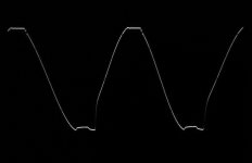
As requested by aparatusonitus, I tried the LM3886 with the compensation recommended by Tom from Neurochrome. And, it absolutely looked good with a gain of 22 (within the recommended gain range) and an 8 Ohm load. 180pF (film) between the two inputs, 49pF+20K in parallel with the 22K feedback resistor. -22 times gain. The supply voltage was regulated +/-35V from an LLC SMPS.
Tests with 8 Ohm load.
Image 1: 1KHz, 60Vpp (just before clipping).
Image 2: 1KHz, 40Vpp.
Image 3: 1KHz, clipping at 64Vpp.
As recommended by Tom, the signals were without instability and the square-wave reproduction almost perfect. Clipping was reached in a regular manner and the clipped levels remained acceptably flat.
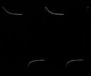
Then, the more questionable test results with 4 Ohm load.
Image 4: 1KHz, 60Vpp and just after turn-on.
Image 5: 1KHz, 60Vpp and a moment later.
Image 6: 1KHz, signal level reduced to 48Vpp (24Vp) and waiting some 15 seconds.
From posting #21 it is seen that until an output level of 22Vp and with a 4 Ohm load, the output remained stable. But when the output level is increased further, instability appears. First I tried the level of 30Vp (60Vpp) but instability appeared just after turn-on (as shown in Image 4) and soon developed to be worse (as shown in Image 5). I then reduced the signal level to 24Vp (48Vpp) and studied the output for some 15 seconds before the positive signal half would suddenly become unstable and collapse, as shown in Image 6 (could be repeated). When that happens as a more severe result of oscillation, the amplifier chip heats up very fast and may suffer damage.
Thus, at higher signal levels and with a 4 Ohm load, instability appears. This could be the result of changed dynamic behavior of the LM3886 chip with higher load current but it may also be due to another reason. I probably misunderstood the LM3886 11.5A (typ.) current limit that appears not to be meant as an operational current limit but rather as a short-circuit current limit. What is then the operational current limit? One way to find out is calculating back from the datasheet specification of 68W in 4 Ohm. 68W in 4 Ohm corresponds to a peak output current of 5.8A. For the test described in Image 6, the peak current level was some 6A and the signal almost stable.
It could be that the instability observed at higher signal levels and with a 4 Ohm load is cause by beginning influence from the current limiter. Similar has been seen with the LM1875. An operational current limit of around 6A is not bad. What is less good is if the chip shows instability near the operational current limit.
It cannot be disputed that the LM3886 has an exceptionally good sound when used on its own and ample supporters for that reason. Wizards like Tom may be able to tame the LM3886 with their exceptional knowledge. For less experienced DIYers, it seems not an obvious choice in a composite amplifier because the challenge of controlling the LM3886 will take most of the effort and as a mere power buffer its performance is not unprecedented.
As requested by aparatusonitus, I tried the LM3886 with the compensation recommended by Tom from Neurochrome. And, it absolutely looked good with a gain of 22 (within the recommended gain range) and an 8 Ohm load. 180pF (film) between the two inputs, 49pF+20K in parallel with the 22K feedback resistor. -22 times gain. The supply voltage was regulated +/-35V from an LLC SMPS.
Tests with 8 Ohm load.
Image 1: 1KHz, 60Vpp (just before clipping).
Image 2: 1KHz, 40Vpp.
Image 3: 1KHz, clipping at 64Vpp.
As recommended by Tom, the signals were without instability and the square-wave reproduction almost perfect. Clipping was reached in a regular manner and the clipped levels remained acceptably flat.
Then, the more questionable test results with 4 Ohm load.
Image 4: 1KHz, 60Vpp and just after turn-on.
Image 5: 1KHz, 60Vpp and a moment later.
Image 6: 1KHz, signal level reduced to 48Vpp (24Vp) and waiting some 15 seconds.
From posting #21 it is seen that until an output level of 22Vp and with a 4 Ohm load, the output remained stable. But when the output level is increased further, instability appears. First I tried the level of 30Vp (60Vpp) but instability appeared just after turn-on (as shown in Image 4) and soon developed to be worse (as shown in Image 5). I then reduced the signal level to 24Vp (48Vpp) and studied the output for some 15 seconds before the positive signal half would suddenly become unstable and collapse, as shown in Image 6 (could be repeated). When that happens as a more severe result of oscillation, the amplifier chip heats up very fast and may suffer damage.
Thus, at higher signal levels and with a 4 Ohm load, instability appears. This could be the result of changed dynamic behavior of the LM3886 chip with higher load current but it may also be due to another reason. I probably misunderstood the LM3886 11.5A (typ.) current limit that appears not to be meant as an operational current limit but rather as a short-circuit current limit. What is then the operational current limit? One way to find out is calculating back from the datasheet specification of 68W in 4 Ohm. 68W in 4 Ohm corresponds to a peak output current of 5.8A. For the test described in Image 6, the peak current level was some 6A and the signal almost stable.
It could be that the instability observed at higher signal levels and with a 4 Ohm load is cause by beginning influence from the current limiter. Similar has been seen with the LM1875. An operational current limit of around 6A is not bad. What is less good is if the chip shows instability near the operational current limit.
It cannot be disputed that the LM3886 has an exceptionally good sound when used on its own and ample supporters for that reason. Wizards like Tom may be able to tame the LM3886 with their exceptional knowledge. For less experienced DIYers, it seems not an obvious choice in a composite amplifier because the challenge of controlling the LM3886 will take most of the effort and as a mere power buffer its performance is not unprecedented.
Attachments
-
 LM3886_1KHz_48Vpp_4Ohm.jpg264.8 KB · Views: 73
 -
 LM3886_1KHz_60Vpp_4Ohm_2.jpg561.8 KB · Views: 316
 -
 LM3886_1KHz_60Vpp_4Ohm_1.jpg430.5 KB · Views: 321
 -
 LM3886_1KHz_Clip64Vpp_8Ohm.jpg439.4 KB · Views: 324
 -
 LM3886_1KHz_40Vpp_8Ohm.jpg315.7 KB · Views: 323
 -
 LM3886_1KHz_60Vpp_8Ohm.jpg275.1 KB · Views: 331
TDA7293
Intrigued by the somewhat questionable reaction of the LM3886 IC to what appears to be current limitation, I decided to test the behavior of the TDA7293 at current limitation. I had already my 500W, +/-35V LLC power supply connected and with that the output current limit should be reached in a 4 Ohm load.
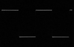
The typical current limit value of the TDA7293 is stated to be 6.5A. With a 4 Ohm load that means sine-wave peaks at 26V. I used a 1KHz sine-wave test signal.
Image 1 shows the result.
The output signal passed 26Vp, corresponding to the typical current limit of 6.5A, and continued to 29.5Vp (slightly decreasing when the chip heated up) before a flat clipping-zone appeared. I tried it more times and the effect was every time the same. 29.5V in 4 ohm corresponds to a current (limit) of 7.3A. A good margin to the 6.5A specified.
Honestly, this is the kind of behavior I appreciate from a current limiter – full performance to the limit, then keeping that limit-level without any unpredictable phenomena such as random oscillation.
If two TDA7293 are connected with the output stages in parallel, it seems very likely that they together can handle more than 13A because the current is split between two ICs. 13A can deal with almost any speaker impedance and leaves the possibility to add one more TDA7293 output stage if needed. BTL-coupling will in most cases not be needed.
Due to voltage drop of my unregulated +/-48V supply, I only really tried the TDA7293 with +/-40V supply voltage. At that supply voltage level, the TDA7293 still behaved predictably.
It seems like a good chip-amp candidate when a composite amplifier with a higher output level is needed.
Image 1: 1KHz output (current) clipping at 59Vpp in a 4 Ohm load.
Intrigued by the somewhat questionable reaction of the LM3886 IC to what appears to be current limitation, I decided to test the behavior of the TDA7293 at current limitation. I had already my 500W, +/-35V LLC power supply connected and with that the output current limit should be reached in a 4 Ohm load.
The typical current limit value of the TDA7293 is stated to be 6.5A. With a 4 Ohm load that means sine-wave peaks at 26V. I used a 1KHz sine-wave test signal.
Image 1 shows the result.
The output signal passed 26Vp, corresponding to the typical current limit of 6.5A, and continued to 29.5Vp (slightly decreasing when the chip heated up) before a flat clipping-zone appeared. I tried it more times and the effect was every time the same. 29.5V in 4 ohm corresponds to a current (limit) of 7.3A. A good margin to the 6.5A specified.
Honestly, this is the kind of behavior I appreciate from a current limiter – full performance to the limit, then keeping that limit-level without any unpredictable phenomena such as random oscillation.
If two TDA7293 are connected with the output stages in parallel, it seems very likely that they together can handle more than 13A because the current is split between two ICs. 13A can deal with almost any speaker impedance and leaves the possibility to add one more TDA7293 output stage if needed. BTL-coupling will in most cases not be needed.
Due to voltage drop of my unregulated +/-48V supply, I only really tried the TDA7293 with +/-40V supply voltage. At that supply voltage level, the TDA7293 still behaved predictably.
It seems like a good chip-amp candidate when a composite amplifier with a higher output level is needed.
Image 1: 1KHz output (current) clipping at 59Vpp in a 4 Ohm load.
Attachments
Thanks FF for that effort!
are these test with caps at the ouput ? no if i read correctly.
you wrote that the 3886 is more stable with cap. load?
chris
Hi Chris,
Most of my tests are without capacitors at the output. Only where I have written a capacitance value, the output was loaded with that capacitance.
For a start you need to ensure that an amplifier is stable with a purely resistive load. Then, you test how sensitive it is to capacitive loading.
I hope I did not write something wrong. Actually, TDA7293 was close to oscillation (permanent) with 10nF directly at the output while LM3886 would oscillate permanently with 10nF directly at the output. So, TDA7293 is handling capacitive loading a little better than LM3886 but both need a Thiele compensation network to operate with real speakers because both are too sensitive to capacitive loading.
Did I write otherwise?
Last edited:
Hi Chris,
Most of my tests are without capacitors at the output. Only where I have written a capacitance value, the output was loaded with that capacitance.
For a start you need to ensure that an amplifier is stable with a purely resistive load. Then, you test how sensitive it is to capacitive loading.
I hope I did not write something wrong. Actually, TDA7293 was close to oscillation (permanent) with 10nF directly at the output while LM3886 would oscillate permanently with 10nF directly at the output. So, TDA7293 is handling capacitive loading a little better than LM3886 but both need a Thiele compensation network to operate with real speakers because both are too sensitive to capacitive loading.
Did I write otherwise?
no, no you are right !...as always...
i mixed it....sorry
- Status
- This old topic is closed. If you want to reopen this topic, contact a moderator using the "Report Post" button.
- Home
- Amplifiers
- Chip Amps
- Chip-amps suited as power stage in a composite amplifier, LM1875/TDA2050 excluded.