I would like to build TDA7294 in bridge mode, anyway started researching in google about the circuit, i have practically started to feel dizzy.
I found at least 20 different circuits of TDA7294 in bridge mode, and now I don't feel comfortable of doing it just like that, because I fear of failing..
Just - picking in the dark in definitely not my thing.
Please, if someone have done this circuit, and it is working fine - share it, and any thoughts on it would be perfect help.
Thank You in advance.
TDA7294 in bride mode seems only relevant if you want really high power. If it is the high power that is important, consider a class D amplifier instead. You will have much less heating problems
If you want a high power class AB amplifier disregarding the heating, consider a uPC1342V based amplifier with external power transistors because your heat distribution will be better.
If you really want to use TDA7294, consider TDA7293 instead. TDA7293 can be connected in parallel using a master-slave structure. With TDA7294 and bridge mode, you may soon be short of current capacity.
In such case, try to look for an amplifier based on IRS2092S (class D). They are made up to 1000W. You cannot make them cheaper yourself than buying two assembled amplifier modules and make a power supply yourself. The power supply will be the most expensive.
A heatsink for a bridged TDA7293/7294 will cost as much as an IRS2092S amplifier module. Building it yourself from scratch will be difficult.
NB: A TDA7294 or TDA7293 cost around 2$. They are useful for amplifiers to around 100W. What costs is heatsinks and power supply.
A heatsink for a bridged TDA7293/7294 will cost as much as an IRS2092S amplifier module. Building it yourself from scratch will be difficult.
NB: A TDA7294 or TDA7293 cost around 2$. They are useful for amplifiers to around 100W. What costs is heatsinks and power supply.
Last edited:
If your speaker is 8R then bridged or parallel can give you ~200W max with a pair of TDA7293. Different power rail voltages of course for each solution. If the load is below 8R then don't even think of bridged, parallel is the way to get the maximum power.
500W is out of the question with just two chips.
500W is out of the question with just two chips.
Yes. I am aware of all of this. I am just looking for a circuit for a TDA7294 in bridge mode which is proven to be working please. :'(
I only have TDA7293 working in normal SE mode. I have no experience with any such bridge circuit. Sorry!
What's wrong with the application circuit in the DS (figure 25)?
:| To be honest I am not sure which one referencing. Please link it.
( I am quite new in this forum yet, so maybe I am not fully understanding the link ideologies in here yet )
well.. the problem is that this is a referent circuit. None of the referent circuits from the original documents I've done so far went as good as expecting. That's why I am looking for something which is done for real from someone and he can point to the possible flaws of the thing.
A yeah. Aside of this, I am not sure as well about the "Mute" port. Why I have to definitely use it, and why I have to connect it to 18V ?!..
( I am in uPC's circuits and programming and those things is quite weird and new to me, and that's why I am looking for suggestions )
( I am in uPC's circuits and programming and those things is quite weird and new to me, and that's why I am looking for suggestions )
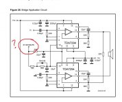
That's the mute/standby control - needs to go to +5V to turn it on. 0V to disable the amp - see page 9. Seems anything above 3.5V will turn the amp on, all the way up to the supply voltage.
If you don't use it and just wire those pins (9,10) to the positive supply then you'll likely get turn on/turn off thumps, pops or clicks.
If you don't use it and just wire those pins (9,10) to the positive supply then you'll likely get turn on/turn off thumps, pops or clicks.
".. the problem is that this is a referent circuit. None of the referent circuits from the original documents I've done so far went as good as expecting."
Ummmm, this worries me.
If you honestly believe that the manufacturer of an IC does not know how to apply the device in a design, I am not sure where to start helping you! How do you think the manufacturer generated the specifications on the datasheet?
If on the other hand you are acknowleding issues in your implementation of the recommended designs, you might be best starting with a kit from an electronics supplier or with some pre-built boards from ebay/aliexpress/etc.
".. the problem is that this is a referent circuit. None of the referent circuits from the original documents I've done so far went as good as expecting."
Ummmm, this worries me.
If you honestly believe that the manufacturer of an IC does not know how to apply the device in a design, I am not sure where to start helping you! How do you think the manufacturer generated the specifications on the datasheet?
If on the other hand you are acknowleding issues in your implementation of the recommended designs, you might be best starting with a kit from an electronics supplier or with some pre-built boards from ebay/aliexpress/etc.
I come here looking for ready circuit, which were done by someone, not theorizing, and pointlessly pointing toward someone which you probably do not know, without reason. Aside of this I am not expecting any help more than a simple tested circuit.
If You have done the referent circuit, and there is no issues with it - I will took my words back, anything else, different from a simple "have done this" schematic ( a picture ) on the topic is pointless discussion with none positive results for anyone. So - if You do not meet the criteria of the topic - do not interfere in it.
Last edited:
That's the mute/standby control - needs to go to +5V to turn it on. 0V to disable the amp - see page 9. Seems anything above 3.5V will turn the amp on, all the way up to the supply voltage.
If you don't use it and just wire those pins (9,10) to the positive supply then you'll likely get turn on/turn off thumps, pops or clicks.
That's a good points @abraxalito !!! Noted it!
") Thank YOU !
Thank YOU !I did build something very similar to the reference circuit in a commercial application over 20 years ago. Due to the distance in time my memory of the schematic isn't super-clear but on the reference design I didn't much like the fact that the inverted phase was fed from the output of the 'true' phase. I figured that any distortion from the 'top' amp would be compounded at the output of the 'inverted' amp. So what I built was effectively two incarnations of the top topology (non-inverting) and fed each one with signals 180o out of phase, created with an opamp inverter (gain of -1).
I did build something very similar to the reference circuit in a commercial application over 20 years ago. Due to the distance in time my memory of the schematic isn't super-clear but on the reference design I didn't much like the fact that the inverted phase was fed from the output of the 'true' phase. I figured that any distortion from the 'top' amp would be compounded at the output of the 'inverted' amp. So what I built was effectively two incarnations of the top topology (non-inverting) and fed each one with signals 180o out of phase, created with an opamp inverter (gain of -1).
Well. That's a way more better dialog. Notes taken. Thank You!
Last edited:
- Status
- This old topic is closed. If you want to reopen this topic, contact a moderator using the "Report Post" button.
- Home
- Amplifiers
- Chip Amps
- TDA7294 in bridge mode?