As mentioned in another thread, I ended up with a UPC1342V based diy kit, kinda accidentally when I was aiming for LM3886 but i carried on with it anyway.
After numerous problems, broken drill bits and new tool purchases I finally got it working, just powered up on the kitchen table without inputs or outputs.
After a few minutes i could smell the heat coming from the amp chips, and after a few more the heatsink was too hot to touch.
The heatsinks themselves are huge, at 12 x 30 x 5cm and I think my diy skills are adiquate since the heat is obviously transferring to them.
Upon asking the seller (taobao) for advice I was told the heat is pretty normal, and than I could lower the power, to reduce the heat.
His info on how to do this was confusing to say the least, since it's in chinese and even after translating, I don't have a clue.
Kinda tempted to scrap the whole idea and go for my original 3886 idea, but it means new PSU, new amp boards and probably new case/s since I'll probably rethink the whole idea, but before I think about that. Does anyone have a clue what the normal process would be to reduce the power/heat in a chipset like this? The boards themselves are 150watt, which is more than I need so I can sacrifice some output if it means it operates more like an amp and less like a heater.
Thanks in advance...")
After numerous problems, broken drill bits and new tool purchases I finally got it working, just powered up on the kitchen table without inputs or outputs.
After a few minutes i could smell the heat coming from the amp chips, and after a few more the heatsink was too hot to touch.
The heatsinks themselves are huge, at 12 x 30 x 5cm and I think my diy skills are adiquate since the heat is obviously transferring to them.
Upon asking the seller (taobao) for advice I was told the heat is pretty normal, and than I could lower the power, to reduce the heat.
His info on how to do this was confusing to say the least, since it's in chinese and even after translating, I don't have a clue.
Kinda tempted to scrap the whole idea and go for my original 3886 idea, but it means new PSU, new amp boards and probably new case/s since I'll probably rethink the whole idea, but before I think about that. Does anyone have a clue what the normal process would be to reduce the power/heat in a chipset like this? The boards themselves are 150watt, which is more than I need so I can sacrifice some output if it means it operates more like an amp and less like a heater.
Thanks in advance...
I've found the same board on ebay, with the same info about reducing the power in the description, seemingly translated by the same method I used as the wording is identical:
UPC1342V 2SC5200 2SA1943 220W Mono Power Amplifier Board Kit HiFi Class A Amp | eBay
Material introduction:
The PCB is double-sided immersion gold, the power tube is the original Toshiba 2SC5200 2SA1943 2 pairs, NOVER 10000uF 50V Gold Electrolytic Fever Capacitor, the bridge stack is Japan Sanken 50A, the resistance is Beijing 718 copper foot resistor, the other capacitor is Panasonic or Nihon Chemical, the input coupling capacitor is WIMA Germany.
Drive core UPC1342, made in Japan, because of the discontinuation, can only be equipped with the tested disassemble or inventory module, the effect is still very good.
Power supply range: AC18X2 - AC36X2
Because the output tube in parallel, you can output 120W 8 ohm power or 220W 4 ohm power
Output power: According to the different voltage and speaker impedance . the output power is different 20-150w;
when AC35v power supply, output power can be 130w * 2/8 ohm , 200w * 2/4 ohm .
PCB size: 150X72MM
Signal to noise ratio: 105dB, noise level: 0.4mV
The debugging is very simple, only need to adjust the quiescent current, you can adjust the voltage drop across the two white resistors to 20--100MV, enough heat can be adjusted to pure class A.
Package Included:
UPC1342V 2SC5200 2SA1943 220W Mono Power Amplifier Board Kit HiFi Class A Amp | eBay
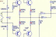
Datasheet ( UPC1342V pdf, UPC1342V description, UPC1342V datasheets, UPC1342V view ::: ALLDATASHEET ::: ), figure on page "434", base-emitter resistor (variable) of Q3 is where the quiescent current can be adjusted.
I see no trim-potentiometer on the board. Would you have an exact diagram of the board circuit?
Can you tell us what is connected between pins 7 and 8 of the IC?
NB: Don't let the components get so hot that you cannot touch them.
I see no trim-potentiometer on the board. Would you have an exact diagram of the board circuit?
Can you tell us what is connected between pins 7 and 8 of the IC?
NB: Don't let the components get so hot that you cannot touch them.
Last edited:
Thanks for the reply, really appreciated.
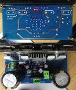
There's a trim pot, I kinda guessed that would be the key to it, but I have no idea where to take the readings from. There are 4 5w resistors
attached a few photos of my board, can you point me in the right direction?
There's a trim pot, I kinda guessed that would be the key to it, but I have no idea where to take the readings from. There are 4 5w resistors
attached a few photos of my board, can you point me in the right direction?
Attachments
Thanks for the reply, really appreciated.
There's a trim pot, I kinda guessed that would be the key to it, but I have no idea where to take the readings from. There are 4 5w resistors
attached a few photos of my board, can you point me in the right direction?
It is a mono chip but you have 4 output transistors and 4 low impedance power resistors. The power transistors are very likely used two and two in parallel to increase current handling and thermal distribution. The four 5W resistors (0.22 Ohm?) are used to balance the currents in the parallel power transistors in the traditional way.
The current in each 5W resistor will be half the total quiescent current because you have two transistors in parallel sharing the current. Less quiescent current leaves less power transistor heating, more quiescent current gives less cross-over distortion. 70mA quiescent current in one push-pull set is usual. That means 140mA for two parallel sets.
Put your voltmeter in the most sensitive DC range and across one of the four 5W resistors. No signal at the input. Adjust the potentiometer to 15mV (dc) on your voltmeter. Check across the three other 5W resistors that you also have 15mV there.
Ready for use.
140mA total quiescent current from a +/-40V supply leaves an idle loss (heating) of more than 11W. Use a really good sized heatsink.
Due to your mentioning of the uPC1342, I have ordered two. One day when I find time, I will try it as well. Fine datasheet specs.
Last edited:
Less quiescent current leaves less power transistor heating, more quiescent current gives less cross-over distortion. 70mA quiescent current in one push-pull set is usual. That means 140mA for two parallel sets.
battery has died in my meter, will try that tomorrow and see if i can salvage this project.
I wont pretend to understand most of the technical information you wrote FauxFrench, but some of it I can follow and i know what i need to do now. You mention lowering the current can cause 'cross over distortion', what is this exactly and how likely is it to be a problem?
Cross-over distortion is inherent in any class AB amplifier (it comes from the class B element). Only using pure class A avoids cross-over distortion. The more quiescent current, the less cross-over distortion (but more heating). As most amplifiers sold in the period 1980-2015 were class AB amplifiers and had cross-over distortion, it is something we have lived with for decades and only very few trained ears will really notice. Don't worry!
Last edited:
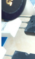
Yes, is it 0r22 or 0r27?0.22 Ohm?
Attachments
Not sure if I am barking up the wrong tree here, but here's my current situation.
My voltmeter is set to 2v range, so I should be looking at lowering the trimpot until it reads 0.015v so its 15mV, correct?
It seems the starting voltage was 440mV, at least with my 'methods'. 440 down to 15 seems...a lot
My voltmeter is set to 2v range, so I should be looking at lowering the trimpot until it reads 0.015v so its 15mV, correct?
It seems the starting voltage was 440mV, at least with my 'methods'. 440 down to 15 seems...a lot
and what do you know, it works!
really surprised, but after 10 minutes of playing an mp3 from an old phone, it was warm, but actually cooler than I expected, so If needs be I could probably raise the power a little.
Now to do the other amp and try and figure out how I'm gonna fit the other bits.
really surprised, but after 10 minutes of playing an mp3 from an old phone, it was warm, but actually cooler than I expected, so If needs be I could probably raise the power a little.
Now to do the other amp and try and figure out how I'm gonna fit the other bits.
and what do you know, it works!
really surprised, but after 10 minutes of playing an mp3 from an old phone, it was warm, but actually cooler than I expected, so If needs be I could probably raise the power a little.
Now to do the other amp and try and figure out how I'm gonna fit the other bits.
The (total) quiescent current you know by measuring the voltage across one 0.25 Ohm/5W resistor, divide this voltage with 0.25 Ohm and multiply by 2 because you have two power transistors in parallel.
That current you can adjust as you like as long as the components and heatsink do not become more than some 45 degrees (Celsius) warm. In principle, the higher quiescent current the less cross-over distortion. But above a certain quiescent current, the cross-over distortion is reduced very little with further increase in quiescent current while the idle power loss increases linearly. The idle power loss is calculated as the total quiescent current times the full supply voltage measured from "+" to "-". It can be quite a lot. Think of "Greta" when you turn the current up
.Anyway, have fun with your newly recovered amplifier/electrical heater.
That current you can adjust as you like as long as the components and heatsink do not become more than some 45 degrees (Celsius) warm. ...
Anyway, have fun with your newly recovered amplifier/electrical heater.
I originally tried to test the temp with a coffee thermometer (hot water probe thing) and I was hitting 70 on the heatsink, that was before I reduced the power though, it seems easily under 45 now.
The other channel, does it use the same heatsink?
well, it does...
The other amp was the first one I powered up before learning of the amps great heating prowess, and at the time I didn't have the heat sink anywhere near set up properly, so after a minute or so I got a whisp of smoke before I pulled the plug on it. I'm not sure if it was just some plastic casing that melted or something more serious...but...
I rewired it up just now, with a correctly set up heatsink and after a few seconds, one of the resisters burnt out, with a bright flame and a pleasant aroma of toast. I'm not sure now if that's a repercussion from the first turn on, or something new.
Looks like I'll put the amp on hold again, although I can still work on the preamp section with my one working channel. Will order another kit and give it one last try. The kit itself is pretty cheap as it doesn't come with capacitors, presuming mine are still OK.
I understand this is frustrating. I think you need to identify the minimum current setting on the pot and set up your case and wiring. High current can come later.
I have a 15x30x5cm heatsink. Two channels, just under 1A each, +/-24V rails so that's about 90W. The heatsinks get very warm but not hot.
Your resistors don't look like 5W resistors (maybe I'm struggling with the photo). 440mV would be creating less than 1W. This could be a problem.
Is there a chance you could get a variac, or make a light bulb tester? What about substituting a different transformer for testing? It is good to see a circuit with reduced voltage so you can see it is in order at low dissipation.
well, it does...
The other amp was the first one I powered up before learning of the amps great heating prowess, and at the time I didn't have the heat sink anywhere near set up properly, so after a minute or so I got a whisp of smoke before I pulled the plug on it. I'm not sure if it was just some plastic casing that melted or something more serious...but...
I rewired it up just now, with a correctly set up heatsink and after a few seconds, one of the resisters burnt out, with a bright flame and a pleasant aroma of toast. I'm not sure now if that's a repercussion from the first turn on, or something new.
Looks like I'll put the amp on hold again, although I can still work on the preamp section with my one working channel. Will order another kit and give it one last try. The kit itself is pretty cheap as it doesn't come with capacitors, presuming mine are still OK.
If it gets so hot that it smokes, the transistors are probably ruined. Ruined may mean short-circuited. If short-circuited, the power resistors may have much more voltage across them and they burn.
With a modest price and unless you are experienced with amplifier fault finding, you better buy a new module. Else you have to find and order replacement parts, await arrival etc....
- Status
- This old topic is closed. If you want to reopen this topic, contact a moderator using the "Report Post" button.
- Home
- Amplifiers
- Chip Amps
- reduce power to reduce heat from UPC1342V kit