But +NE5534 in a composite?Just the 1875 alone...
What kind of layout did you use? Can you provide a picture?
And congrats to those numbers!
That is quite something if you are able to tame those oscillations.
Its this proto with unknown compensation, as I cant remember any longer...
I just threw in the resistor between input pins of the LM and resistor to ground from pin 1. The ones I first got my hands into... 330 and 1500 I think...
Lets see if I can get THD to below the range of my system again (0.0005%)...
I just threw in the resistor between input pins of the LM and resistor to ground from pin 1. The ones I first got my hands into... 330 and 1500 I think...
Lets see if I can get THD to below the range of my system again (0.0005%)...
Attachments
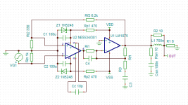
In posting #572, I tested the genuine LM1875 and found that a 470-820 Ohm resistor should be put between the two input pins (no capacitor in series) depending on the gain (-3 or -5). I also used a 1K resistor to ground from the non-inverting input. See the last picture in that posting. That combination I found to be without oscillation and with a very good square-wave response.
Thanks for the hint. That looks like a promising candidate and I agree that an integrated switch makes life/PCB-layout at least a little easier.
LTC3780 would make a nice generic "power block" as it is buck&boost and could be used for a number of amps.
A transfomer+buck/boost-converter is still simpler than a AC/DC-SMPS.
I personally would like a regulated PSU as it doesn´t suffer from sagging rail voltages like a linear PSU.
There are ready-made modules on eehbay and amasin (XL4015/XL4016/LTC3780) just like the LM2596 which I have a few of.
Cheap as chips but apparently the LTC3780-ones are more expensive and don´t seem very well built.
I might give the XL4016 a try and yes, please report your findings about the design.
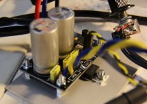
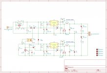
I finally received the parts for my power supply V2. It’s now much more beefy and can handle the composite amp at full power. Schematic attached.
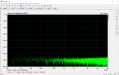
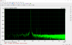
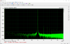
Some measurements :
- noise floor at -97dB.
- THD @ 8Ω / 10.4Vrms : 13.5W (with +/- 17.8V supply) : 0.0026%
- THD @ 4 Ω / 9Vrms : 20W (with +/- 17.8V supply) : 0.0050%
Adding a post filter to the PSU clearly remove switching noise on the rail but has neglectful impact on measured THD (few 100s ppm of THD).
What could matter is output impedance of PSU : at full power I measure close to 100mVpp of “audio in the rails”: image of the input signal in the supply rails, minus and positive ones, even if they have different switcher architecture : one is buck other is buck boost inverter. Unfortunately, I’ve no linear supply to make a comparison.
I’m currently waiting for some polymer caps to replace the output caps of PSU, but I don’t expect much improvement : current caps have already very low ESR : Pana FC.
This is enough for this project, I’ll install it in my Arta box / desktop amp and start to enjoy it.
Chris
Attachments
Last edited:
Thank you joensd !
I use a Focusrite Scarlett 2i2 V3, which is announced @111dB dynamic. I’ve read that Scarletts embed CS4272 Codec announced @114dB / 24 bits. Not bad for Focusrite to reach figures so close to the ones of the codec used.
This amp project is my first time ‘serious’ usage of this Focusrite to measure amp THD (I’ve used it for now only for speakers) and I’ve learned some very practical aspects, for those kinds of measurements:
- Very high sensitivity to the quality of the cables (mainly connectors) tied to input and output of the sound card. I put some to garbage and made new ones and everything went better !
- Very high sensitivity to electrical environment: I always have to remove my DMM from the circuit (it certainly acts as an antenna) same for scope (I obviously have ground loops with PC). The Best measures are made when less device are connected to the DUT and no electrical device is close to the DUT and associated cables. Beginning with cell phone !
I use a Focusrite Scarlett 2i2 V3
Thanks, that´s good to know.I’ve used it for now only for speakers
I´ve been thinking either the really cheap route via Behringer UCA202 or the Focusrite Solo for THD measurements but also for my Dayton IMM-6 mic.
The mic I only use it with a phone app so far and it´s not the most convenient way of measuring speakers.
Hi,
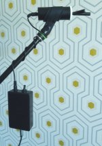
I also have a Dayton IMM-6.
I bought it to use with my Focusrite for speaker projects.
I've made an electrical and mechanical adapter to suit usual mike dimensions and also convert TRRS to TRS jack in order to use standard 3.5 mm stereo jack cable. For this, I use a medic tab tube. I also made a battery powered mike preamp with LN JFET and ST TS472 chip.
Works ok, but I've no mean to ensure that Dayton IMM-6 calibration file is ok and stable over time...
Attachments
Hi Chris,
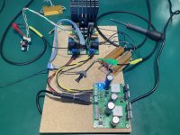
I didn't change the amplifier, except the input wiring with the JST connector and the two cinchs, but I used a new supply. Results could certainly be improved with a linear supply and with a different pcb layout.
I haven't made serious testing with my main speakers, I will. On my test setup it has strong bass and provide clear listening even in complex situation with lot of instruments even at high power (high remains reasonable : below 20W...") ). It is not as good as my ongoing TAS3251 project, but it doesn't play in the same category.
). It is not as good as my ongoing TAS3251 project, but it doesn't play in the same category.
Chris
I didn't change the amplifier, except the input wiring with the JST connector and the two cinchs, but I used a new supply. Results could certainly be improved with a linear supply and with a different pcb layout.
I haven't made serious testing with my main speakers, I will. On my test setup it has strong bass and provide clear listening even in complex situation with lot of instruments even at high power (high remains reasonable : below 20W...
). It is not as good as my ongoing TAS3251 project, but it doesn't play in the same category.Chris
- Home
- Amplifiers
- Chip Amps
- LM1875 in parallel configuration and used in a composite amplifier.