To not take this further off-topic, I started a new thread for the TDA7293:
https://www.diyaudio.com/forums/chip-amps/368974-source-layout-tda7293-composite-amp.html#post6562839
https://www.diyaudio.com/forums/chip-amps/368974-source-layout-tda7293-composite-amp.html#post6562839
Take a look at the data sheet , +40 -40v you will get into 8 ohms no more than 60w with 0.1% distortion .The TDA7293 can absolutely max. handle +/-50V. I assumed clipping at +/-40V. That is with a supply voltage of +/-43V. I wouldn't take it further.
Attachments
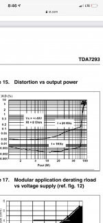
You are right. But, when we state a maximum output power we need to have a common understanding of what are the conditions. Old HiFi (DIN45500) norm used 1%, today many use 10% and some 0.1% or less. Then we cannot compare performance.
10% is for me unrealistic because at that level the distortion is noticeable for (almost) everybody.
1% is in the order of slight clipping and the level where "ordinary" people start hearing distortion.
0.1% and below is for enthusiasts, which is absolutely fine.
I use "slight clipping" (voltage) as criterion because it is definable for all types of amplifiers.
0.1% or better is relevant for performance level at normal listening level, thus, 0.5-5W. I doubt you would like to be in front of speakers consuming 60W average anyway.
Even 1% distortion in a rare transient would probably be accepted even by enthusiasts because there will be a limit somewhere.
So, we fully understand one another. I just use slight clipping as level and calculated for 4 Ohm. (power in 8 Ohm should be about half).
Last edited:
Composite Amp
Hi,
Thank you FauxFrench and Cheerman for your work about TDA2050 or LM1875 composite amp.
Based on it, I’ve built a little amp, not parallel because I don’t need much power, mainly targeted to be my ArtaBox amp and also desktop amp for the desktop speaker I’m building. This is 99% your design.
As it should be powered by a laptop a power brick (20V), I also made a symmetrical supply on LM2596. It’s ok for testing or for low to mid power usage but lacks power and has too much forward voltage drop (between 1.5 and 2.5V for the positive rail). A new version is a coming which should be able to handle continuously +/- 18V @ 3A. PCB and parts are awaited soon.
I use TDA2050, not made UTC but by HGSEMI, they behave as you described. In order to guarantee stability minimum noise gain has to be set to 30dB (680Ω between neg and pos inputs of TDA). With noise gain set to 24dB (min value stated in the datasheet) chip may trigger oscillation when it leave the negative clipping area (what you show in the thread).
Sound quality is very good, night and day with than non-composite implementation !, and also silent, despite usage of SMPS. I should now do some measurements.
Chris
I am very pleased to hear opinions about the sound quality. Myself I can hear if an amplifier is poor or good. Comparing two good amplifiers I find difficult because for me it depends on the speakers, the type of music, my personal preferences, my mood etc.
Theoretically, the sound should be good because the THD should be particularly low but vacuum tube amplifiers show that sound quality is not only about THD.
Theoretically, the sound should be good because the THD should be particularly low but vacuum tube amplifiers show that sound quality is not only about THD.
I'll be really interested in measurements and maybe some more power supply details.
Hi Joensd
The psu is powered by a laptop power brick delivering 20V-90W. A transformer based supply could also be used, the PSU has a starting circuity which guarantee start up with slow start or/and limited current power source; no NTC required.
The version of the psu shown in previous post deliver a nominal +/-18.5V.
Currently the self are undersized. Thus the inverting buck, which strike much harder than the positive buck, quickly bring the core in saturation which then overheat. This is near 1A on output. Negative LM2596 also overheat, as heatsink are the copper areas used on both side of the PCB.
I’m waiting for new selfs: 33uH / 4A, but I don’t expect miracle on the negative side as, limitation will come from LM2596 current limit and cooling.
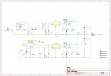
Here’s schematic, with new self and output voltage set to 17V, as 18.5V is not sustainable for positive buck under heavy load where Vcesat of internal bjt switch raise too much.
Despite its structural defects, this PSU allows the composite map to play loud and clean in a little room wick bookshelf speaker, 6Ω. But practically speaking, I won’t use it for more than 1.2A continuously, that why a V2 is on its way, very similar but with more beefy switcher, Schottky and self.
The starter is mandatory for the negative buck which, at startup, require a lot of current. The circuit around the BS170 wait C5 sufficiently loaded through R3, D1 and D4 then start inverting LM2596 and light on optocoupler. The optocoupler allows to unleash full power from the source, by shorting R3, and to start the positive buck converter.
Chris
Attachments
True, the datasheet even mentions 220uF for the normal Buck configuration. The reason for my comment is that when you tie the output of a buck circuit to ground, you effectively implement the inverting configuration with a discontinuous output current in the output capacitor (I did not find that configuration in the datasheet). Therefore, my impression is that the output capacitor of the inverting configuration should have a larger value than when you use the ordinary Buck configuration with continuous output current. With a higher capacitor value, you should have more equal voltage ripple on the two supply rails.
Hi,
Thank you FauxFrench and Cheerman for your work about TDA2050 or LM1875 composite amp.
Based on it, I’ve built a little amp, not parallel because I don’t need much power, mainly targeted to be my ArtaBox amp and also desktop amp for the desktop speaker I’m building. This is 99% your design.
As it should be powered by a laptop a power brick (20V), I also made a symmetrical supply on LM2596. It’s ok for testing or for low to mid power usage but lacks power and has too much forward voltage drop (between 1.5 and 2.5V for the positive rail). A new version is a coming which should be able to handle continuously +/- 18V @ 3A. PCB and parts are awaited soon.
I use TDA2050, not made UTC but by HGSEMI, they behave as you described. In order to guarantee stability minimum noise gain has to be set to 30dB (680Ω between neg and pos inputs of TDA). With noise gain set to 24dB (min value stated in the datasheet) chip may trigger oscillation when it leave the negative clipping area (what you show in the thread).
Sound quality is very good, night and day with than non-composite implementation !, and also silent, despite usage of SMPS. I should now do some measurements.
Chris
View attachment 938882
Cool Chris
 nice that somebody take over this idea...
I am interested in the different gain of your configuration because you wrote you did it like we mentioned. but which version finally?
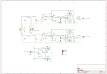
what i remember its fine if you use -3,5 - 5 gain at the power chip and about the opamp 6 -8gain. additionally you use a coil and resistor like at the output like the LM3886.So it would be fine that you show your schematic. thx
SMPS (dual rail)
SMPS is done by fred at the ebay LM1875 kit with no negative feedback by fred. so its is fine. i do not compared the difference between SMPS and a linear unregulated or regulated power supply.
As i use SMPS at my ACA i have read that a 7µ -10µ H big coil helps to "filter" the high freq. noise from the smps. the same as you can find at the class D amps like TPA3255!
plus...if you use an electrolytic polymer 1200µF (high ripple current at 100kHz) after the coil it will be fine.
chris
One should read R15, not R3...
The starter is mandatory for the negative buck which, at startup, require a lot of current. The circuit around the BS170 wait C5 sufficiently loaded through R3, D1 and D4 then start inverting LM2596 and light on optocoupler. The optocoupler allows to unleash full power from the source, by shorting R3, and to start the positive buck converter.
True, the datasheet even mentions 220uF for the normal Buck configuration. The reason for my comment is that when you tie the output of a buck circuit to ground, you effectively implement the inverting configuration with a discontinuous output current in the output capacitor (I did not find that configuration in the datasheet).
Datasheet says 47uF tant or 220uF ecap for inverting buck/boost. (p12 & 13).
As I do not encounter ripple issue, loop stability issue nor in audio band noise, I do not need to change output caps or add post regulator LC filter.
I am interested in the different gain of your configuration because you wrote you did it like we mentioned. but which version finally?
So it would be fine that you show your schematic. thx
Hello Chris,
For main loop gain I use 10, for TDA signal gain I use -4.8 and TDA noise gain of 38.7 (510 Ω).
Measurements will follow.
Chris
Attachments
Chris,
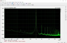
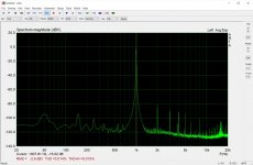
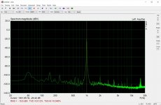
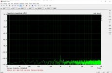
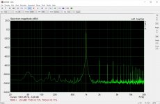
some measurements :
Pic#1 : sound card loopback input shorted (1kHz spike is radiation of the amp to the probe I use)
Pic#2 : -20dB output / 8Ω
Pic#3 : -3dB / 8Ω
Pic#4 : 0dB / 8Ω. Vout peak = 15V (30Vpp), maximum value before clipping begin
Pic#6 : -20dB output / 4Ω
Pic#7: -3dB / 4Ω
No Pic#7 at 0dB / 4Ω as supply drop and amp start clipping
With 8Ω, results are pretty good, but with 4Ω, version 2 of my PSU if definitely required !
Chris
Attachments
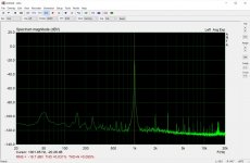
Many thanks for sharing your test results. Those THD figures are not what I hoped to see.
Our Finnish member “palstanturhin” wrote in posting #278 that his measurement with LM1875+NE5534 was below his scope lower limit of 0.001% (-100dB) In posting #292 he further concluded better than 0.0005% (-106dB). Measuring such low THD levels precisely requires very good gear and results have to be “taken with a grain of salt”. Is your loop-back value 0.001% (-100dB)?
Anyway, you soon have a more powerful power-supply that may influence the results.
Unfortunately I cannot measure THD better than in the order of 0.005% at best so I cannot contribute with a value.
At least you seem to like the sound.
Loopback is close to -130dB, sound card is a Scarlett 2i2v3.
I did not expect such high figure you mention, but if those are realistic targets, maybe I should check my test fixture. I sometime encounter weird issues (ground loops ?) when PC and scope are both connected to the same DUT.
I did not expect such high figure you mention, but if those are realistic targets, maybe I should check my test fixture. I sometime encounter weird issues (ground loops ?) when PC and scope are both connected to the same DUT.
... resistor between pin 1+2...
Hi
just a small information by my sound check the last days.
i have done the UTC2050V amp month ago and i did the trick to use a resistor between the inputs at the power chip to avoid cap in the feedback loop and get better square wave response at the output. the utc2050V do not like the same cap as Cf as the LM1875!! i did not test this amp in sound very often
i borrow this amp to my brother (clone F5, and hifi akademie P6) and ask for sound feedback.
His response was following:
nice and detailed sound very clear and focused but what the f*.. is about the sound stage and separation of singers and instruments??? if the music get more complex the stage fell down i can´t relax listening this amp is stressful to listing !
ok thanks i said and i did a listening test at home. yes the sound stage is strange it sound like some times the phase is changing out of phase and in phase -its getting very confused if it get complex.
i did a measurement and see with the square wave a very strange wave form at the output with still low level of output power 5W!!! 4R load no cap! i remember this comment:
https://www.diyaudio.com/forums/chi...ad-lag-compensation-bad-idea.html#post6243493
so i de solder the resistor and try it. i get now 40% later a better square wave at the output and a perfect DC offset. with resistor o got -40mV and now -2mV. but the other channel is still perfect at the same conditions. now i check my caps near the chip. then i see that i have not the same power supply caps on the left and right channel. i remember i use a lot of test boards and after fail of my 2parallel utc 2050 amp i use boards which are working.
the good boards use the panasonic FC 220µF with my mods +33µF panasonic +100nF film + 10nF at the power supply pins to GND under the pcb. the other board i use the rubycon 470F/ ZLH version with the same caps. after try and error all caps the final solution was only the 470µF ruby and my 33µF get the perfect square wave result like the other board!!! i guess i got at this bad board a kind of oscillation by all the caps!! a resonant circuit !!
so if you read the Xmas amp (+ TDA7293 threads)and the comments from more experienced members they wrote that you have to be carefully with "bigger" caps at the power rail near the chip.
now the amp sounds like the other LM1875 amp and its a good cheap amp with use full power.
chris
Hello Chris,
For main loop gain I use 10, for TDA signal gain I use -4.8 and TDA noise gain of 38.7 (510 Ω).
Measurements will follow.
Chris
Thank you chris that's helpful. but please try to avoid the 510 resistor at pin 1 +2.
The Scarlett 2i2V3 is indeed a good unit. I found these specs. for the Scarlett 2i2: Scarlett 2i2 | Focusrite . Here the input level THD+N is stated to 0.002% (-94dB) and the output level THD+N to 0.002% (-94dB) as well. These are absolutely fine values. A loop-back value of -130dB (0.0000316%) seems to be in the reference class. From my very brief search, it is possible to find DACs with down to -130dB THD but very difficult to find ADCs for that level.
My Sound Blaster 24 bit, I can force down to a level around 0.005%. Even a minor flaw in the test setup leaves worse figures. A problem with USB units seems to be that the manufacturers leave the USB +5V to be the main supply voltage for convenience reasons. That leaves sufficient voltage for the DACs and ADCs but even with an ICL7660 voltage pump, the OP-AMPs are somewhat voltage-starved and do not perform to the THD levels we expect.
The levels you measure should absolutely leave good sound for your ears. I suspect your power supply to have an influence on the levels you measure which are on the limit of what your ears can detect. Ordinary people like me hardly detect below 0.1% THD. For measuring very low THD levels you seem to need a "perfect" (very low output impedance and hardly any noise) power supply. Try again with your new power supply when it is ready.
I appreciate very much that you spend time on this LM1875 design. Not a lot of practical experience is available until now. You are the first with a really nice PCB layout.

- Home
- Amplifiers
- Chip Amps
- LM1875 in parallel configuration and used in a composite amplifier.