Hi FF
yes i see your to do list in the other thread...
psu ? i remember your strong regulated psu?..actually distrelec has some transformers at a good price. my brother build his pass F5 with the new bigger PSU boards and a 400VA 18-0-18 transformer - costs about 68euros
300VA 18-0-18VAC 57 euro
%product-title% kaufen
the composite amp is not forgotten by me. i want to go through that because i want to learn how to build this composite e.g. 2x2 1875 or utc
chris
Many thanks for the tip.

I already have other transformers up to some 300VA. I just need to get them mounted in frames with input components and rectification + decoupling capacitors (all ready to be mounted when I find time). I also have a 500W LLC SMPS I could use as supply to my linear regulator if I really wanted to put my triple/BTL at risk. I am "a chicken" and will rather evaluate the sound (controlled by the LM4562) on a working amplifier than knowing I could get 50% more power out before it blew-up. After all, just getting more power isn't so difficult.
Chris, it looks really good. You are a skilled craftsman.
Class D sound I find at level with class AB sound in general. You easily get more power with class D.
What I like about composite class AB in particular is that you have sufficient parameters you can adapt to make your own design and sound while not being as complex as discrete amplifier designs.
Using a class D chip with all included in the chip leaves you limited possibilities to do otherwise than what is intended for the chip.
Last edited:
Many thanks for the tip.
I already have other transformers up to some 300VA. I just need to get them mounted in frames with input components and rectification + decoupling capacitors (all ready to be mounted when I find time). I also have a 500W LLC SMPS I could use as supply to my linear regulator if I really wanted to put my triple/BTL at risk. I am "a chicken" and will rather evaluate the sound (controlled by the LM4562) on a working amplifier than knowing I could get 50% more power out before it blew-up. After all, just getting more power isn't so difficult.
Yep FF, correct
first sound
then power
This will describe the probably last test of my triple-BTL “fake” LM1875 amplifier. The reason is explained below.
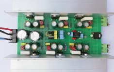
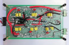
First I made two photos of the amplifier, seen from above and below. As it is quickly noticed, the mono board is quite extensive considering that the maximum output power is in the range 100W-200W. It is due to the use of six LM1875 ICs arranged along the two cooling profiles. In the middle, power rail decoupling capacitors are found along with +/-15V voltage regulators and the controlling LM4562 OP-AMP.
Image 1: The triple-BTL “fake” LM1875 amplifier seen from above.
Image 2: The triple-BTL “fake” LM1875 amplifier seen from below.
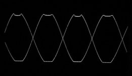
As a last modification I had put two 5V1 zener-diodes, connected back-to-back, between the outputs of the LM4562 OP-AMP and the inputs of the LM1875 power stages. It gave an improved clipping as seen from Image 3:
Image 3: Clipping at 41Vpp using 1KHz and 8 Ohm load (BTL).
The last test was a listening test in a parallel-coupling of two 8 Ohm speakers. BTL coupling to the mono output. An unregulated +/-24V power supply was used.
My pretty inexperienced impression was a solid but firm bass and very clean mid-tone reproduction of vocals. I let the amplifier play for a good hour at medium sound-level. With an idle power-loss of around 20W (due to 6 chip-amps) the amplifier became lukewarm. I was present when the amplifier suddenly made a high-pitch noise and the sound level was reduced with distortion. I immediately switched the amplifier off and let the amplifier cool to room temperature. When I switched the power back on, the amplifier played correctly for a couple of seconds before one of the LM1875 ICs burned with smoke.
It was the amplifier string made last that became defect. It had not been tested as thoroughly as the first string with low impedance loads.
Why this LM1875 IC burned after more than an hour of perfect operation is impossible to say for sure. It could be that this IC suddenly started oscillating when the temperature increased and the load sharing would consequently be lost. It was known that for such “fake” LM1875 ICs overload protection could not be relied upon. In case of overload, the LM1875 is likely to be destroyed.
I know which LM1875 it is and with some difficulty it can be replaced. The problem is that the same thing may happen again as none of my LM1875 are likely to have a functional protection system. If it can happen again, I will need to be next to the amplifier when playing such that I can switch it off in case of new problems. That is not practical.
I managed to do the technical experiments and tests I wanted. Only the listening test could have been more elaborate but anyway my experience is limited. I may isolate the defect string and finalize listening test in SE mode.
It is hardly worth repairing and continuing with this amplifier because “fake” LM1875 ICs are not fully reliable and the further information that could be gained is limited. Better recover the cooling profiles and a few electronic components for a new reliable amplifier, perhaps based on UTC-TDA2050. The UTC-TDA2050 is tested to be reliable.
Accordingly, I will terminate the triple-BTL “fake” LM1875 amplifier.
NB: I will update and post the schematics.
First I made two photos of the amplifier, seen from above and below. As it is quickly noticed, the mono board is quite extensive considering that the maximum output power is in the range 100W-200W. It is due to the use of six LM1875 ICs arranged along the two cooling profiles. In the middle, power rail decoupling capacitors are found along with +/-15V voltage regulators and the controlling LM4562 OP-AMP.
Image 1: The triple-BTL “fake” LM1875 amplifier seen from above.
Image 2: The triple-BTL “fake” LM1875 amplifier seen from below.
As a last modification I had put two 5V1 zener-diodes, connected back-to-back, between the outputs of the LM4562 OP-AMP and the inputs of the LM1875 power stages. It gave an improved clipping as seen from Image 3:
Image 3: Clipping at 41Vpp using 1KHz and 8 Ohm load (BTL).
The last test was a listening test in a parallel-coupling of two 8 Ohm speakers. BTL coupling to the mono output. An unregulated +/-24V power supply was used.
My pretty inexperienced impression was a solid but firm bass and very clean mid-tone reproduction of vocals. I let the amplifier play for a good hour at medium sound-level. With an idle power-loss of around 20W (due to 6 chip-amps) the amplifier became lukewarm. I was present when the amplifier suddenly made a high-pitch noise and the sound level was reduced with distortion. I immediately switched the amplifier off and let the amplifier cool to room temperature. When I switched the power back on, the amplifier played correctly for a couple of seconds before one of the LM1875 ICs burned with smoke.
It was the amplifier string made last that became defect. It had not been tested as thoroughly as the first string with low impedance loads.
Why this LM1875 IC burned after more than an hour of perfect operation is impossible to say for sure. It could be that this IC suddenly started oscillating when the temperature increased and the load sharing would consequently be lost. It was known that for such “fake” LM1875 ICs overload protection could not be relied upon. In case of overload, the LM1875 is likely to be destroyed.
I know which LM1875 it is and with some difficulty it can be replaced. The problem is that the same thing may happen again as none of my LM1875 are likely to have a functional protection system. If it can happen again, I will need to be next to the amplifier when playing such that I can switch it off in case of new problems. That is not practical.
I managed to do the technical experiments and tests I wanted. Only the listening test could have been more elaborate but anyway my experience is limited. I may isolate the defect string and finalize listening test in SE mode.
It is hardly worth repairing and continuing with this amplifier because “fake” LM1875 ICs are not fully reliable and the further information that could be gained is limited. Better recover the cooling profiles and a few electronic components for a new reliable amplifier, perhaps based on UTC-TDA2050. The UTC-TDA2050 is tested to be reliable.
Accordingly, I will terminate the triple-BTL “fake” LM1875 amplifier.
NB: I will update and post the schematics.
Attachments
Good Morning FF
Sorry to hear that. yes with fake chips its ......
its an excellent build!!! now i have an impression how to build this kind of amp - congratulations!!!
once again - Thank you FF for your effort/ and steady explanations. you show us/me what is possible!!!
chris
Sorry to hear that. yes with fake chips its ......
its an excellent build!!! now i have an impression how to build this kind of amp - congratulations!!!
once again - Thank you FF for your effort/ and steady explanations. you show us/me what is possible!!!
chris
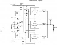
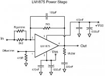
And, the final schematics using the fake LM1875.
NB: As explained in posting #564, the LM1875 that burned harmed two other LM1875 in the string with the opposite phase. No more listening test was possible and the amplifier was disassembled.
NB: As explained in posting #564, the LM1875 that burned harmed two other LM1875 in the string with the opposite phase. No more listening test was possible and the amplifier was disassembled.
Attachments
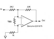
Genuine LM1875
I finally got my hands on genuine LM1875 from Farnell. Genuine LM1875 are not that easy to buy in Europe while more-or-less functional “fakes” can be found in large numbers from Asia at very low prices. But, the performance is rarely similar. My curiosity relates to how much different the genuine LM1875 performs compared to the cheaper (in Europe) but well-performing UTC-TDA2050. Fred and Chris have compared the sound and the difference is marginal as I have understood it. My focus will be on stability at gains below the recommended 20dB and performance of the current limiter. Gains below 20dB can be convenient when used in a composite amplifier.
Image 1: The essential components in the simple test circuit used.
Tests with +/-24V regulated supply, 8 Ohm load, -10 times gain (inverting; 2K2/22K).
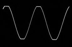
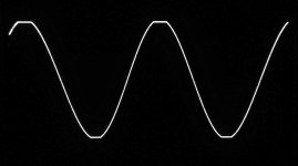
Image 2: Square-wave response at 20KHz, 20Vpp, no resistor between the input pins.
Quite some ringing was observed. The ringing could be reduced much by connecting a resistor between the two input pins.
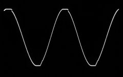
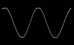
Image 3: Square-wave response at 20KHz, 20Vpp, 2K2 resistor between the input pins.
Image 4: Sine-wave at 20KHz, clipping at 44Vpp, 2K2 resistor between the input pins.
Image 5: Sine-wave at 1KHz, clipping at 44Vpp, 2K2 resistor between the input pins.
For test of the current limiting function, the load had to be reduced to 4 Ohm. 2K2 resistor between the input pins.
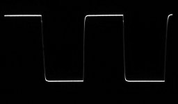
Image 6: Sine-wave at 1KHz, (current) clipping at 38Vpp in 4 Ohm. 2K2 resistor between the input pins.
The clipping at 38Vpp, probably caused by the current limiter, with a 4 Ohm load means clipping at 4.7A peak. Better than promised in the datasheet. Nice flat clipping.
I then tried to lower the load-impedance further to 3.2 Ohm (two 8 Ohm resistors and one 16 Ohm resistor in parallel).
Image 7: Sine-wave at 1KHz, current clipping at 34Vpp in 3.2 Ohm. 2K2 resistor between the input pins.
Though not fully symmetrical, 34Vpp in 3.2 Ohm corresponds to 5.3A peak! Much better than expected and approaching the current handling of the UTC-TDA2050. The protection functionality seems to include chip-temperature protection such that the current limit was reduced short after permanent use of the current limiter.
The -3dB bandwidth was measured to about 460KHz at 4Vpp, with the 2K2 resistor between the two input pins.
Also sensitivity to capacitive loading of the output was tested with the 2K2 resistor between the input pins. 10nF showed no oscillation while 100nF was found to be about the limit where temporary oscillation started. Not bad but a Thiele compensation network is recommended.
Next posting, test of the genuine LM1875 with gains of -5 and -3…………….
I finally got my hands on genuine LM1875 from Farnell. Genuine LM1875 are not that easy to buy in Europe while more-or-less functional “fakes” can be found in large numbers from Asia at very low prices. But, the performance is rarely similar. My curiosity relates to how much different the genuine LM1875 performs compared to the cheaper (in Europe) but well-performing UTC-TDA2050. Fred and Chris have compared the sound and the difference is marginal as I have understood it. My focus will be on stability at gains below the recommended 20dB and performance of the current limiter. Gains below 20dB can be convenient when used in a composite amplifier.
Image 1: The essential components in the simple test circuit used.
Tests with +/-24V regulated supply, 8 Ohm load, -10 times gain (inverting; 2K2/22K).
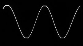
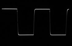
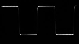
Image 2: Square-wave response at 20KHz, 20Vpp, no resistor between the input pins.
Quite some ringing was observed. The ringing could be reduced much by connecting a resistor between the two input pins.
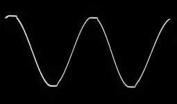
Image 3: Square-wave response at 20KHz, 20Vpp, 2K2 resistor between the input pins.
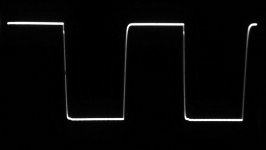
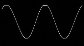
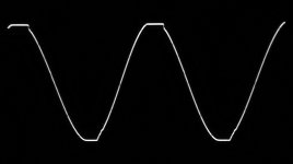
Image 4: Sine-wave at 20KHz, clipping at 44Vpp, 2K2 resistor between the input pins.
Image 5: Sine-wave at 1KHz, clipping at 44Vpp, 2K2 resistor between the input pins.
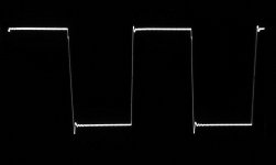
For test of the current limiting function, the load had to be reduced to 4 Ohm. 2K2 resistor between the input pins.
Image 6: Sine-wave at 1KHz, (current) clipping at 38Vpp in 4 Ohm. 2K2 resistor between the input pins.
The clipping at 38Vpp, probably caused by the current limiter, with a 4 Ohm load means clipping at 4.7A peak. Better than promised in the datasheet. Nice flat clipping.
I then tried to lower the load-impedance further to 3.2 Ohm (two 8 Ohm resistors and one 16 Ohm resistor in parallel).
Image 7: Sine-wave at 1KHz, current clipping at 34Vpp in 3.2 Ohm. 2K2 resistor between the input pins.
Though not fully symmetrical, 34Vpp in 3.2 Ohm corresponds to 5.3A peak! Much better than expected and approaching the current handling of the UTC-TDA2050. The protection functionality seems to include chip-temperature protection such that the current limit was reduced short after permanent use of the current limiter.
The -3dB bandwidth was measured to about 460KHz at 4Vpp, with the 2K2 resistor between the two input pins.
Also sensitivity to capacitive loading of the output was tested with the 2K2 resistor between the input pins. 10nF showed no oscillation while 100nF was found to be about the limit where temporary oscillation started. Not bad but a Thiele compensation network is recommended.
Next posting, test of the genuine LM1875 with gains of -5 and -3…………….
Attachments
-
 LM1875Gen_1KHz_CurClip34Vpp_10x_2K2_3R2.jpg243.6 KB · Views: 65
 -
 LM1875Gen_1KHz_CurClip38Vpp_10x_2K2_4R.jpg283.2 KB · Views: 51
 -
 LM1875Gen_1KHz_Clip44Vpp_10x_2K2.jpg300.5 KB · Views: 58
 -
 LM1875Gen_20KHz_Clip44Vpp_10x_2K2.jpg302.8 KB · Views: 58
 -
 LM1875Gen_20KHz_20Vpp_10x_2K2.jpg268.4 KB · Views: 61
 -
 LM1875Gen_20KHz_20Vpp_10x_NoRes.jpg292.3 KB · Views: 113
 -
 GenLM1875Handling.jpg15.7 KB · Views: 202
Last edited:
You get a very good amp for about three Euro...
These fakes really suck. One could argue "it is only an audio chip and these poor Chinese just want to make a living".
The same guys faking these chips fake airplane parts, brake pads, live saving medicament´s and anything where they see a profit.
They are not poor people from a developing country you can smile about, but some of the worst criminals on the planet.
I have to throw up if I see their always stupidious smiling leader.
You get a very good amp for about three Euro...
These fakes really suck. One could argue "it is only an audio chip and these poor Chinese just want to make a living".
The same guys faking these chips fake airplane parts, brake pads, live saving medicament´s and anything where they see a profit.
They are not poor people from a developing country you can smile about, but some of the worst criminals on the planet.
I have to throw up if I see their always stupidious smiling leader.
Hi Turbowatch2,
I must admit that for the LM1875, it makes a very big difference if you use what appears to be genuine but in reality is "fake" or you manage to get the real genuine ones. For the time being Farnell has them and delivery is for free above 30 Euro (ex.VAT).
The genuine LM1875 has a much better current capability than I expected (OK, I only tested one specimen) and when taking an LM1875 to the limits in test, it is really nice to know that the protection part works.
I did not imagine that the issue of "fakes" was so extended. You are right, for any serious construction use "genuine" if possible. It will save you some worries.

Hi FF
Fine that your 1875 arrived and work very well. As i remember to avoid a early hit the current limiter is to reduce the voltage supply < = 25V and 4R or less are working well.
chris
Hi Chris,
Yes, you are right about our conclusion at that time. They may still be valid but I will try to take my genuine LM1875 to +/-28V regulated supply at the end of testing. +/-28V supply may be an advantage (a little extra power / use of a non-regulated power supply) when using an 8 Ohm load. Perhaps the LM1875 datasheet is prudent and real performance is better than what can be assumed from the datasheet.
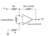
Genuine LM1875
Continued from posting #567.
The feedback resistor was changed for a gain of -5 (inverting; 2K2/11K).
Tests with +/-24V regulated supply, 8 Ohm load and -5 times gain.
Image 1: Square-wave response at 20KHz, 20Vpp, 820R resistor between the input pins.
Image 2: Sine-wave at 20KHz, clipping at 44Vpp, 820R resistor between the input pins.
Image 3: Sine-wave at 1KHz, clipping at 44Vpp, 820R resistor between the input pins.
The feedback resistor was subsequently changed for a gain of -3 (inverting; 2K2/6K6).
Tests with +/-24V regulated supply, 8 Ohm load and -3 times gain.
Image 4: Square-wave response at 20KHz, 20Vpp, 470R resistor between the input pins.
Image 5: Sine-wave at 20KHz, clipping at 44Vpp, 470R resistor between the input pins.
Image 6: Sine-wave at 1KHz, clipping at 44Vpp, 470R resistor between the input pins.
Both with gains of -5 and -3, the genuine LM1875 performs very well as long as the resistor between the two input pins is adapted to the gain.
The -3dB bandwidth at 4Vpp was measured to around 380KHz. The limit for capacitive loading of the output was around 1uF.
As promised to Chris, the genuine LM1875 was at the end tried with a regulated +/-28V power supply. The gain used was -5 and the load 8 Ohm.
Image 7: Square-wave response at 20KHz, 20Vpp, 820R resistor between the input pins.
Image 8: Sine-wave at 20KHz, clipping at 50Vpp, 820R resistor between the input pins.
Image 9: Sine-wave at 1KHz, clipping at 50Vpp, 820R resistor between the input pins.
At the clipping limit, the power in the 8 Ohm load was 39W. That is a very respectable value. The square-wave response at +/-28V supply hardly changed and indicates a moderate change of dynamical behavior with supply voltage.
I tested the current limiter more times, with gains of -5 and -3, and in all cases the current limiter functioned well such as described in posting #567. Even with the +/-28V supply, the performance remained unchanged.
Finally I decided to see how much power I could get in an 8 Ohm load. I raised the supply voltage to +/-29.5V (regulated). At 1KHz, I measured 54Vpp corresponding to 45W in 8 Ohm!
Image 10: The essential components in the circuit tested.
Conclusion:
The genuine LM1875 performed much better than I had expected from my first experience with “fake” LM1875. The genuine ones have protection features that work and the genuine chip can handle much more current than “fake” items, even more than stated in the datasheet. The functioning of the current limiter is logical and reliable judged from test of only one specimen.
Compared to the UTC-TDA2050 it is a close run. The genuine LM1875 can handle higher supply voltages which is an advantage with 8 Ohm loads. The UTC-TDA2050 seems to handle capacitance at the output a little better than the genuine LM1875 and is somewhat cheaper, at lest in Europe. Both chip-amps are highly recommend for those who only need moderate output power, in an ordinary design or in a composite amplifier. Both can be used in parallel and BTL configurations such that power levels well above 100W can be reached. But, such combinations may increase the components count and result in high idle currents for which reason LM3886 or TDA7293 may be better choices.
Attachments
-
 GenLM1875HandlingFinal.jpg18.1 KB · Views: 201
 -
 LM1875Gen_1KHz_Clip50Vpp_5x_820R_8Ohm.jpg280.5 KB · Views: 96
 -
 LM1875Gen_20KHz_Clip50Vpp_5x_820R_8Ohm.jpg306.9 KB · Views: 75
 -
 LM1875Gen_20KHz_20Vpp_5x_820R_8Ohm_28V.jpg252.9 KB · Views: 86
 -
 LM1875Gen_1KHz_Clip44Vpp_3x_470R_8Ohm.jpg491.2 KB · Views: 78
 -
 LM1875Gen_20KHz_Clip44Vpp_3x_470R_8Ohm.jpg303.9 KB · Views: 424
 -
 LM1875Gen_20KHz_20Vpp_3x_470R_8Ohm.jpg244.3 KB · Views: 452
 -
 LM1875Gen_1KHz_Clip44Vpp_5x_820R_8Ohm.jpg564.2 KB · Views: 442
 -
 LM1875Gen_20KHz_Clip44Vpp_5x_820R_8Ohm.jpg262.2 KB · Views: 440
 -
 LM1875Gen_20KHz_20Vpp_5x_820R_8Ohm.jpg258.3 KB · Views: 465
This is what I expected: The real chips have been permanently improved over the very long production time. So tolerances between chips of one batch will be near to non existing. The actual performance should be better than the (once) projected performance you see in the data sheet.
This is a simple logic in Western industry production. If you can do better, do it. If your products do not fail, you have no cost in the service department.
If you do not have a service department, because you are a criminal producing fake dirt, you do not care for quality. The Eastern version of a business model.
Hi FF
As the genuine1875 performing better i have a question. in your post #566
you show the power stage with a 100pF as Cf and no R between PIN 1 and 2.
in the new schematic (last post) you wrote that the Rf and the R between the pin 1 and pin2 should fit and the performance is very good, no cap Cf.
so does this mean that the 100pF is not necessary any more and for building this power stage is better to use the R between PIN 1,2 ?? (in the last post. #572)
thx
chris
Hi Chris,
I will suggest the resistor and not the 100pF capacitor for a genuine LM1875, at least when used in a composite amplifier.
The 100pF was my way of slowing a "fake" LM1875 down in order to reduce overshoot. The 100pF does not influence static offset at the output.
The resistor was what I found later to be a general method of increasing chip-amp stability. But, it has a price on output offset and may as well have a price on loop-gain for the chip-amp itself. Meaning that THD may increase a little which is not a problem if you use it in a composite amplifier where the controlling OP-AMP performs the main THD reduction. Larger output offset is also not a problem with a controlling OP-AMP that easily compensates for the offset at the output.
So for a composite amplifier, use the resistor for increase of stability.
For a simple LM1875 amplifier without a controlling OP-AMP, try first without a resistor between the input pins and without a 100pF capacitor. This is what is proposed in the datasheet. Then you can try adding the resistor, measure if the output offset is reasonable and if you can hear a difference.
In some cases, the 100pF actually makes the overshoot worse or even provokes oscillation.
Last edited:
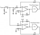
Hi to all
here is the 3p(arallel) 1875 BTL-schmatic version drawn in Kicad. i plan to design a complete board but its very new for me (last was 1994) so i need time") . the board should be on one pcb 2 layer.
. the board should be on one pcb 2 layer.
the last weeks the progress was not so fast but FF helped me to make this schematic final - thank you FF!
his board you will find here:
https://www.diyaudio.com/forums/chi...ation-composite-amplifier-57.html#post6157862
i planned to use directly the 3900µF caps at every power chip because you get the euro chemicon with 35V much cheaper as some bigger caps with this high.
the welcome caps are the rail decoupler and have to be on the board - i found that that are the best form money and size. my target is to have a max high of about 55mm. Cornell Dubilier SLPX223M035H4P3 - 4,30 euro
i need your advice about some resistor value of Power (0,25, 0,6W1W,2W,5W...etc)of some feedback resistors. read here:
https://www.diyaudio.com/forums/chi...ripped-version-compact3886-4.html#post6008444
so my idea is to use 1% metal film and big as possible through hole (THT) resistors for best performance
R3 and R19 feedback resistors for the complete feedback power stage (3p)
1Watt ok?
R10 - R12, R26-R28 feedback resistors at every power chip
1Watt ok?
rx4+rx11 feedback resistor at the opamp - 0,6W ok i guess
zobel and output balance resistors are clear for me...2W and 5W (wounded)
all other resistor are in my layout design list 0,25W -ok?
i you have some good ideas for better values, or 0,5% cheaper or company name give me a hint -
if you find something wrong - give me a hint
other ideas are welcome
thanks
chris
here is the 3p(arallel) 1875 BTL-schmatic version drawn in Kicad. i plan to design a complete board but its very new for me (last was 1994) so i need time
. the board should be on one pcb 2 layer.the last weeks the progress was not so fast but FF helped me to make this schematic final - thank you FF!
his board you will find here:
https://www.diyaudio.com/forums/chi...ation-composite-amplifier-57.html#post6157862
i planned to use directly the 3900µF caps at every power chip because you get the euro chemicon with 35V much cheaper as some bigger caps with this high.
the welcome caps are the rail decoupler and have to be on the board - i found that that are the best form money and size. my target is to have a max high of about 55mm. Cornell Dubilier SLPX223M035H4P3 - 4,30 euro
i need your advice about some resistor value of Power (0,25, 0,6W1W,2W,5W...etc)of some feedback resistors. read here:
https://www.diyaudio.com/forums/chi...ripped-version-compact3886-4.html#post6008444
so my idea is to use 1% metal film and big as possible through hole (THT) resistors for best performance
R3 and R19 feedback resistors for the complete feedback power stage (3p)
1Watt ok?
R10 - R12, R26-R28 feedback resistors at every power chip
1Watt ok?
rx4+rx11 feedback resistor at the opamp - 0,6W ok i guess
zobel and output balance resistors are clear for me...2W and 5W (wounded)
all other resistor are in my layout design list 0,25W -ok?
i you have some good ideas for better values, or 0,5% cheaper or company name give me a hint -
if you find something wrong - give me a hint
other ideas are welcome
thanks
chris
Attachments
Last edited:
here are my part lists with the different size the get the final layouting....
at some components i try to find some options
chris
at some components i try to find some options
chris
Attachments
Hi Chris,
R3, R19, overall feedback resistors, power loss 5mW max. thus, 0.5W or higher should be fully sufficient.
R10 - R12, R26-R28, local feedback resistors, power loss 32mW max. thus, 0.33W or higher is fine. Inside the feedback loop so the OP-AMP will compensate any thermal distortion from these resistors.
rx4+rx11, stability feedback resistors at the opamp, only high-frequency current for stabilization, thus, 0.25W or higher is fine.
zobel and output balance resistors are clear for me...2W and 5W (wounded), not wounded (harmed/injured) -> wire-wound (wound/turned around a body).
Metal film, but I am not aware of different qualities for ordinary use.
Last edited:
- Home
- Amplifiers
- Chip Amps
- LM1875 in parallel configuration and used in a composite amplifier.