Good to know...UTC 2050 are since 5 days at my bench...no test actually. +/- 25V max
the only concern what i have is that the 18VAC transformer gives about 26,7 Volts at idle with 2 mono boards and 8 ohm speakers. i used my open baffle 12/5 but the second woofer per side is of -so i have just 8R load.
the voltage drops at loud listening just short (heavy bass) at 24,4V....to closed i think.
the lm1875 is able to handle more Voltage but gets after my test with 25V and higher current earlier problems instead of +/-22V. (ebay kit thread).
chris
I listened to the amplifier with all the test music from before and I could not hear any difference from last test.
You mean to say, between the composite and non composite versions?
Originally posted by FauxFrench:
That exactly comfirms my findings!
Did you perhaps also check the dissipation/ temperature of the chip?
Given the very similar results you experienced (in comparison to the "LM1875") and the current limit of 5A peak of the UTC-TDA2050 isn't this chip the preferred choice?
Two paralleled UTC's will probably give comparable results to three LM1875's which might simplify the project somewhat.
Also the working built-in protections are an advantage at (almost) comparable cost.
Hi Fred,
I come to the same results as you. Two can be used in BTL coupling with an 8 Ohm load and an output power of some 70W or four in parallel/BTL with a 4 Ohm load and an output power of 120W. Fully enough for most. 1 Eur a piece and moderate delivery costs. Just what we need.
When I have finished this 3x2 fake LM1875 I will try the 2x2 UTC-TDA2050V just to confirm our findings. I will also think about a better amplitude clamp for the OP-AMP. Like that, a very well performing amplifier can be made with a modest budget. Letś hope the supplies from Taiwan are not being disturbed by the very sad situation on the continent.
I am very happy that you suggested this IC. I did not know about this active second source.
You mean to say, between the composite and non composite versions?
No, my last test was also composite but without amplitude clamp. I need to do an A<>B test to know if I can actually distinguish a plain LM1875 from a composite version. Or better, we let someone who has had his ears washed more recently than I, someone like Chris
 , do the comparison.
From what I have heard yet with my test-board, it is flawless.
No, my last test was also composite but without amplitude clamp. I need to do an A<>B test to know if I can actually distinguish a plain LM1875 from a composite version. Or better, we let someone who has had his ears washed more recently than I, someone like Chris
From what I have heard yet with my test-board, it is flawless.
It sure is looking good on the scope! Interesting to see how much faster the op-amp is, I'm looking forward to seeing how this ends.
Good to know...UTC 2050 are since 5 days at my bench...no test actually. +/- 25V max
the only concern what i have is that the 18VAC transformer gives about 26,7 Volts at idle with 2 mono boards and 8 ohm speakers. i used my open baffle 12/5 but the second woofer per side is of -so i have just 8R load.
the voltage drops at loud listening just short (heavy bass) at 24,4V....to closed i think.
the lm1875 is able to handle more Voltage but gets after my test with 25V and higher current earlier problems instead of +/-22V. (ebay kit thread).
chris
We could consider a regulated power supply, eventually as integrated part of the amplifier board. The one I use is homemade and a suitable regulator is not difficult to make. You can run a regulated version from most transformers you salvage from a broke-down AVR amplifier, found on a dumb. I even know a way to use two rather similar transformers in parallel for double current. I like re-use.
We could consider a regulated power supply, eventually as integrated part of the amplifier board. The one I use is homemade and a suitable regulator is not difficult to make. You can run a regulated version from most transformers you salvage from a broke-down AVR amplifier, found on a dumb. I even know a way to use two rather similar transformers in parallel for double current. I like re-use.
Do you think about a LM317 and 337? - the max current is "just" 1,5A each rail. or you have a transistor additionally for more current...
turbowatch wrote that its a second best solution to use the existing transformer and add 2 diode to "waste" - 1,4V each rail...
i ahve no idea how much a rail can be sag if more then 2 chips are in operation. fix is that a UTC 2050 has max 25V supply.
An alternative to a buffered LM317/LM337 supply is an LLC SMPS similar to the one Fred uses, with +/-24V, and then add a "voltage dropper" before the decoupling capacitors. Diodes can be used.
A traditional unregulated power supply can be less useful if you build a power version because you have to stay below 25Vdc under all circumstances and that will drop importantly when current is drawn at higher power levels.
A traditional unregulated power supply can be less useful if you build a power version because you have to stay below 25Vdc under all circumstances and that will drop importantly when current is drawn at higher power levels.
The SMPS i am using has a variable output voltage of +-21V to 29V, adjustable with a small potentiometer on board, so imo no further voltage dropping circuits or diodes etc are required.
Yes i can wholeheartedly recommend the SMPS. The max output specified is (about) 2x25V at 5A ie about 250W.
But for this project a "sister" power supply has an additional +/- 15v (max 1 A) supply onboard - for feeding eg the composite opamp(s).
See the following link: SMTP click
For this project obviously an advantage
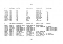
Some thoughts on chip-amps suited for composite designs. (Only to be read by the most patient)
Almost any chip-amp can be used as power stage in a composite amplifier design. Clearly with huge difference in power level, significant difference in sound and variation in the amount of trouble making the composite amplifier work.
The chip-amp candidates I prefer are chosen such that they can operate from a symmetrical supply voltage, which makes connection to the controlling OP-AMP straight forward. Further, they have a level of output power from 20W and upwards, have low THD in particular for the high frequency range and are easy to purchase at a moderate cost. Also, it should be possible to control the gain with external components such that those chip-amps with an internally set gain are excluded.
Below in the appended scheme you find a number of candidates. Further candidates were considered but excluded for different reasons. Among those excluded are LM2876. Though equipped with modern control and protection features, LM2876 performs as amplifier at the level of LM1875. Another is the LM3876 that appears to be a power-limited version of the LM3886 but with no apparent benefits for composite amplifier use.
I have listed characteristics for each chip-amp that appear of particular importance.
Supply voltage. The absolute maximum operational voltage is listed. How well the chip-amp is working in practice at the maximum supply voltage is another matter and a lower supply voltage will in most cases be chosen for safe and trouble-free operation. The maximum operational supply voltage is crucial for the potential output power such that the maximum operational supply voltage is a very relevant indicator for output power. The TDA729X ICs using DMOS output appears to go closer to the supply rails with the output voltage than the other chip-amps.
Channels lists the number of amplifiers in a single IC. If an IC includes two channels (two amplifiers), these two amplifier channels may be connected for parallel operation (this is marked as dual) such that the output current capability is increased (generally doubled). If more ICs have to be connected in parallel to increase current handling, this is marked as double.
Maximum current lists the current limit for a single amplifier output. If one IC includes two channels (two amplifiers), the combined (paralleled) output current is generally double that of a single channel. The maximum current is as essential for the maximum output power as the maximum supply voltage.
While the maximum supply voltage determines how much current can be forced through a load with a certain impedance, the maximum current decides if that will actually be allowed or current limitation will instead reduce the current. The maximum current can be increased by connecting two channels in one chip in parallel (“dual”) or connecting two ICs in parallel (“double”).
THD at 10KHz is important for the composite amplifier performance. As I recall teaching in regulated systems many years ago, the remaining “error” in a regulated system is in large the initial “error” in the loop divided by the gain in the loop (at that frequency). Please correct me if I am wrong. Thus, the purpose of the controlling OP-AMP in a composite amplifier is to increase loop-gain, with very little distortion from the OP-AMP itself, in a regulated loop including a power amplifier such that the “error (distortion) from the power amplifier is reduced by the total loop-gain, mainly provided by the OP-AMP, and resulting in that the distortion of the power amplifier is reduced importantly.
But, the regulation loop gain is frequency dependent in order to keep the regulation loop stable. Also, the power amplifier distortion level depends on the frequency. The normal way of reducing gain in such a regulation loop (to keep the loop stable) is to connect a capacitor from the output of the OP-AMP and back to the inverting input of the OP-AMP. This local feedback for the OP-AMP means that the gain of the OP-AMP in the regulated loop reduces with 6dB per octave or 20dB per decade when increasing frequency.
Finding a suitable value for the OP-AMP feedback capacitor used in my triple LM1875 with an LM4562 OP-AMP left me with a value of 100pF and a total loop-gain at 1KHz above 100. Let us assume 100 when continuing. This means that the power amplifier (triple LM1875) distortion at 1KHz is reduced with 100 (40dB). If the initial distortion in the triple LM1875 is 0.02% at 1KHz, the OP-AMP regulation loop should reduce it to 0.0002%. Very good! But due to the feedback capacitor, the OP-AMP gain at 10KHz is only 1/10th of the gain at 1KHz, thus 10 (20dB). Further, distortion in chip-amps tends to increase for high frequencies. Let's assume that my triple LM1875 has a distortion of 0.06% at 10KHz. With a loop-gain of 10, that distortion is reduced to 0.006%. Not bad at all but not at the extremely low value for 1KHz. The regulation loop becomes less-and-less efficient the higher in frequency we go. What can be done about that? Nothing, apart from choosing a power amplifier (chip-amp) with an initially low THD at high frequencies (10KHz used here) such that the regulation loop has less to correct. This is why I have added this chip-amp characteristic in the scheme. Once more LM3886 is doing very well (0.01%).
Minimum gain (in the chip-amp) is important for matching the gains in the regulation loop. Most chip-amps are stated in the datasheet only to be stable at a gain above 10 (20dB). Some even need a higher gain to be stable. For ensuring the optimum working conditions for the OP-AMP, the power amplifier (chip-amp) gain should be in the range 3-6 and not 10 or more. Evidently, we could use a resistive voltage divider at the output of the OP-AMP, before the power amplifier, and thereby compensate for the too high gain in the power amplifier. But, it is not an ideal solution as a high gain in the power amplifier results in a higher noise level. Two experienced forum members knew that the LM1875 could be used considerable below a gain of 10. In an inverting configuration, the LM1875 shows surprising stability down to a gain of around -3. Then, no voltage divider is needed and there will be less noise at the output due to less power amplifier gain. This is why I added this column. Only for the LM1875 and the TDA2050 I know of such experience at present. How other chip-amps than the LM1875/TDA2050 will handle a gain below 10 is at present unknown.
Power SE 8 Ohm / SE 4 Ohm / BTL 8 Ohm / BTL 4 Ohm lists theoretical output power levels (“abs max” / absolute maximum) estimated from datasheets graphs and/or maximum supply voltage levels and maximum current levels. These power values are in many cases not realistic for practical operation but indicates only the potential of each chip-amp relative to the other. It is indicated if “dual” (two channels in the same chip) needs to be used or if “double” (two separate ICs) is required.
No chip-amp cost are taken into account. I will add some comments in a subsequent posting.
NB: The above is considering low THD which is not directly related to good sound.
Attachments
Referring to posting #510:
LM1875. In the low end power-wise as it is advised not to use this chip above +/-25V supply. Some self-oscillation tendencies have been observed that may relate to the current limiter. Low THD at 10KHz and very good sound on its own. Needs to be connected in parallel even for SE use with 4 Ohm load unless the supply voltage is reduced further. For BTL use, it is advised not to go below 8 Ohm as load impedance. Can be bought as “fake” at very low prices in which case the current limiter does often not work and short-circuit of the output is likely to destroy the chip. Stable in inverting coupling down to a gain of -3.
TDA2050. Not supplied anymore by ST but from a former second-source company, “Unisonic” in Taiwan, under the product name UTC-TDA2050V. Can be bought for a very modest price at Reichelt in Germany. The performance is very close to that of LM1875 but a supply voltage above +/-23V should not be used. Slightly higher THD at 10KHz than for LM1875. The advantage of TDA2050 compared to LM1875 is that the current limit is at 5A and not 4A such that a single TDA2050, used in SE coupling, can handle both 8 and 4 Ohm loads. Two TDA2050 ICs in BTL coupling can handle an 8 Ohm load. The over-current and temperature protections seem to work well. Appears to be stable down to a gain around -3, like for the LM1875, but more tests are needed.
The obvious candidate for a low cost solution with only very few minor concessions. “Fake” TDA2050 bought extremely cheap are not worth the bother compared to the still cheap UTC-TDA2050V with reliable performance.
TDA7293. One of the last class AB chip-amps being produced by ST that is not intended for automotive use. The class AB top product from ST and with some unusual features. The most unique feature is the use of DMOS power transistors in the output. The result is, according to the datasheet, that the output can get closer to the supply rails than for chip-amps with bipolar transistors in the output. This means more output power for the same supply voltage if correct. Next, TDA7293 output stages can be connected in parallel without use of load balancing resistors through a master-slave feature. While the supply voltage range is very generous, the output current limit only allows use of an 8 Ohm load before another TDA7293 output stage needs to be connected in parallel. High power levels can be achieved but substantial cooling is needed. The THD at 10KHz is low. The real gain range needs to be tested. Very modest price seen in the light of the performance.
TDA7294. A power reduced version of the TDA7293 and without the master-slave feature. Also with DMOS output stage allowing the output to go closer to the supply voltages according to the datasheet. To be tested.
TDA7295. A power reduced version of the TDA7294. Also with DMOS output stage allowing the output to go closer to the supply voltages according to the datasheet. To be tested.
TDA7296. A power reduced version of the TDA7295. Also with DMOS output stage allowing the output to go closer to the supply voltages according to the datasheet. To be tested.
LM3886. Frequently used in composite amplifiers and for an obvious reason. Very low THD at 10KHz and the highest current limiter value (11.5A typ.) such that two LM3886 ICs in BTL coupling can deliver up to 300W in an 8 Ohm load. Bipolar output stage. Can be compared to two TDA7293 with the output stages arranged in parallel. Gain range needs to be tested. Cooling may be an issue at high power levels because the current handling is very high for a single IC. Sold at a very reasonable price considering the top level performance.
LM1876. A very well sounding dual channel IC. Low THD at 10KHz. A bit like two LM1875 in a single housing. For practical use, both channels need to be connected in parallel to allow sufficient current. It needs to be tested if the gain range is the same as for the LM1875. A good IC for moderate power levels.
TDA7265. A steady work-horse sold at a very attractive price. THD at 10KHz higher than for the others. With the two channels connected in parallel, you have a decent high-power handling amplifier for a very modest price when used in BTL configuration. Gain range to be tested.
TDA1514A. The now abandoned class AB top chip-amp from Philips/NXP. Still to be bought and probably as “genuine”. The datasheet seems to reflect the philosophy that the less you promise, the less problems you have afterward. No THD at 10 KHz information. Used by Linn in an amplifier of theirs, the “Majik”. Actual gain range to be tested.
LM4766. Appears to be the most powerful dual-channel chip-amp from TI. Low THD at 10KHz. With the two channels connected in parallel, almost 200W in 8 Ohm can be achieved using two ICs in BTL coupling. Actual gain range to be tested.
The choice is yours!
Yes this is a great summary! I enjoyed reading it, and I am happy to see the TDA1514A on the list. I respect Philips' philosophy but I'm curious what the distortion at 10kHz is!
Note that when Linn stopped using the TDA1514A they moved on to the TDA7293, which also appeared in some excellent sounding amplifiers. The thing which has me curious about the 7293, is the 50V maximum rail voltage. Although the data sheet does not directly say it, I think this means that 3 of them in parallel could put out considerable power into 8 ohms or 4 ohms and avoid the need to do any bridging entirely.
Note that when Linn stopped using the TDA1514A they moved on to the TDA7293, which also appeared in some excellent sounding amplifiers. The thing which has me curious about the 7293, is the 50V maximum rail voltage. Although the data sheet does not directly say it, I think this means that 3 of them in parallel could put out considerable power into 8 ohms or 4 ohms and avoid the need to do any bridging entirely.
Yes this is a great summary! I enjoyed reading it, and I am happy to see the TDA1514A on the list. I respect Philips' philosophy but I'm curious what the distortion at 10kHz is!
")
Attachments
I see -62dB, or 0.0794% for 20W power at 8ohms at 10kHz.
So better than car oriented chips but not as good as the LM3886, etc.
Thanks so much for that document!!
Last edited:
.....................................................
Although the data sheet does not directly say it, I think this means that 3 of them in parallel could put out considerable power into 8 ohms or 4 ohms and avoid the need to do any bridging entirely.
For the TDA7293, I would use two or three in parallel (only output stages), as you suggest, and no BTL coupling. The parallel-coupling ensures ample current capability to handle any normal speaker impedance and the output power is fully sufficient.
I have listed theoretical possibilities (limits). Personally, I would not design for more than around 100W of power. At more hundred Watts, cooling becomes and issue. If really needed, think class D instead.
I see -62dB, or 0.0794% for 20W power at 8ohms at 10kHz.
So better than car oriented chips but not as good as the LM3886, etc.
Thanks so much for that document!!
Many thanks to you both, one more value for my scheme.
I see -62dB, or 0.0794% for 20W power at 8ohms at 10kHz.
I see -72dB or 0.0251% for the same condition as well as -65dB or 0.0562% for 25W/4ohms (hint: vertical scale has 4dB division), also it's not clear whether measurements are done with or without bootstrapped cap
For the TDA7293, I would use two or three in parallel (only output stages), as you suggest, and no BTL coupling. The parallel-coupling ensures ample current capability to handle any normal speaker impedance and the output power is fully sufficient.
I have listed theoretical possibilities (limits). Personally, I would not design for more than around 100W of power. At more hundred Watts, cooling becomes and issue. If really needed, think class D instead.
I need at maximum 75W of power, but 100 is a nice round number. I thought I needed more, but I have not come close to clipping the 33W Linn Majik-I since installing it in my system.
I see -72dB or 0.0251% for the same condition as well as -65dB or 0.0562% for 25W/4ohms (hint: vertical scale has 4dB division), also it's not clear whether measurements are done with or without bootstrapped cap
You know, I figured all that out, but misread the Y axis label as -50dB instead of-60dB because of how the 6 has a flat top. From context though it is obvious you are correct. This is quite good news, 10dB is a big deal, I think I want to use the TDA1514A in mine.
- Home
- Amplifiers
- Chip Amps
- LM1875 in parallel configuration and used in a composite amplifier.