Hi FF
thank you for your explanation. i follow exactly your instruction.
heat sink is a 10mm thick 150mm x100mm plate. and yes i cold the chip with fan but if it gets too hot i moved the fan directly to the chip 10mm ahead.
......
Then, same setup but this time with a load of 8-10 Ohm. 8-10 Ohm with 25V supply will not reach the 4A limit of the LM1875 and not even the test limit of 3A due to the voltage drop in the output stage (2-5V depending on the current). So, clipping should happen near 4V below the supply voltage and the sine-wave look fine until then. A bit of "wool" at the flat tops. If still OK, you continue.
Now 4-5 Ohm loading. With 4 Ohm loading, the 3A test limit is reached at 12V peak and the 4A limit at 16V peak. We know up front that there will be problems at high amplitude. You increase the amplitude until it starts looking strange which should be from 15-16V peak. When the limit is reached you note the limit and lower the amplitude not to stress the chip from increased heating. Current limitation is activated so you cannot rely on nice flat tops.
The big mess starts when you use a load that you have used before but which will cause current limitation, you let the chip heat up significantly so you are not sure how it behaves, the unregulated supply voltage sags and it all looks weird for which reason you declare the chip "fake". You simply lost overview.
no. i used my rigol DP832 (180Watt) and that has no problems with supply.
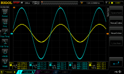
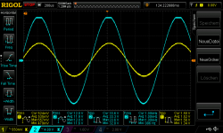
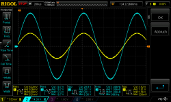
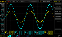
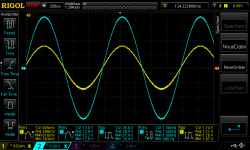
test result look fine:
pic 1 20V supply ampR2_no load_570mVrms input
pic 2 20V supply ampR2_8,67R_520mVrms input
pic 3 20V supply ampR2_8,67R_550mVrms input_clipping
pic 4 20V supply ampR2_4,9R_510mVrms input
pic 5 22V supply ampR2_no load 630mVrms input
pic 6 22V supply ampR2_8,67R 590mVrms input
pic 7 22V supply ampR2_4,9R_540mVrms input
thx
chris
thank you for your explanation. i follow exactly your instruction.
heat sink is a 10mm thick 150mm x100mm plate. and yes i cold the chip with fan but if it gets too hot i moved the fan directly to the chip 10mm ahead.
......
Then, same setup but this time with a load of 8-10 Ohm. 8-10 Ohm with 25V supply will not reach the 4A limit of the LM1875 and not even the test limit of 3A due to the voltage drop in the output stage (2-5V depending on the current). So, clipping should happen near 4V below the supply voltage and the sine-wave look fine until then. A bit of "wool" at the flat tops. If still OK, you continue.
Now 4-5 Ohm loading. With 4 Ohm loading, the 3A test limit is reached at 12V peak and the 4A limit at 16V peak. We know up front that there will be problems at high amplitude. You increase the amplitude until it starts looking strange which should be from 15-16V peak. When the limit is reached you note the limit and lower the amplitude not to stress the chip from increased heating. Current limitation is activated so you cannot rely on nice flat tops.
The big mess starts when you use a load that you have used before but which will cause current limitation, you let the chip heat up significantly so you are not sure how it behaves, the unregulated supply voltage sags and it all looks weird for which reason you declare the chip "fake". You simply lost overview.
no. i used my rigol DP832 (180Watt) and that has no problems with supply.
test result look fine:
pic 1 20V supply ampR2_no load_570mVrms input
pic 2 20V supply ampR2_8,67R_520mVrms input
pic 3 20V supply ampR2_8,67R_550mVrms input_clipping
pic 4 20V supply ampR2_4,9R_510mVrms input
pic 5 22V supply ampR2_no load 630mVrms input
pic 6 22V supply ampR2_8,67R 590mVrms input
pic 7 22V supply ampR2_4,9R_540mVrms input
thx
chris
Attachments
-
 2_20V supply ampR2_no load_570mVrms input.png49.4 KB · Views: 212
 -
 2_20V supply ampR2_8,67R_520mVrms input.png49.6 KB · Views: 208
 -
 2_20V supply ampR2_8,67R_550mVrms input_clipping.png49 KB · Views: 216
 -
 2_20V supply ampR2_4,9R_510mVrms input.png47 KB · Views: 214
 -
 2_22V supply ampR2_no load 630mVrms input.png50.5 KB · Views: 208
 -
 2_22V supply ampR2_8,67R 590mVrms input.png49.8 KB · Views: 44
 -
 2_22V supply ampR2_4,9R_540mVrms input.png49 KB · Views: 37
As suggested by Chris in posting #399, 2.7 Ohm in parallel with 100nF or 1uF.
Still my unregulated power supply with +/-24V.
Picture 1: 1KHz, 20Vpp, 2.7 Ohm in parallel with 100nF
Picture 2: 1KHz, clipping, 2.7 Ohm in parallel with 100nF
Picture 3: 1KHz, 20Vpp, 2.7 Ohm in parallel with 1uF
Picture 4: 1KHz, clipping, 2.7 Ohm in parallel with 1uF
In conclusion, the triple LM1875 is pretty unimpressed by capacitive loading.
 impressive "monster" 3p1875
tried again to parallel my tda2050 (st)..........
first trial was with connected inputs (there are input caps in the signal path) - bad experience.
and now is the connection "behind" the input caps, so the two +in of the opamps are tied together (dc-wise as shown in the bpa data sheet).........it works. turned the volume up loud to clipping, no problems.
Last edited:
tried again to parallel my tda2050 (st)..........
first trial was with connected inputs (there are input caps in the signal path) - bad experience.
and now is the connection "behind" the input caps, so the two +in of the opamps are tied together (dc-wise as shown in the bpa data sheet).........it works. turned the volume up loud to clipping, no problems.
I am very happy to hear that they could be paralleled. Could your eventually post us a sketch of the successful circuit?
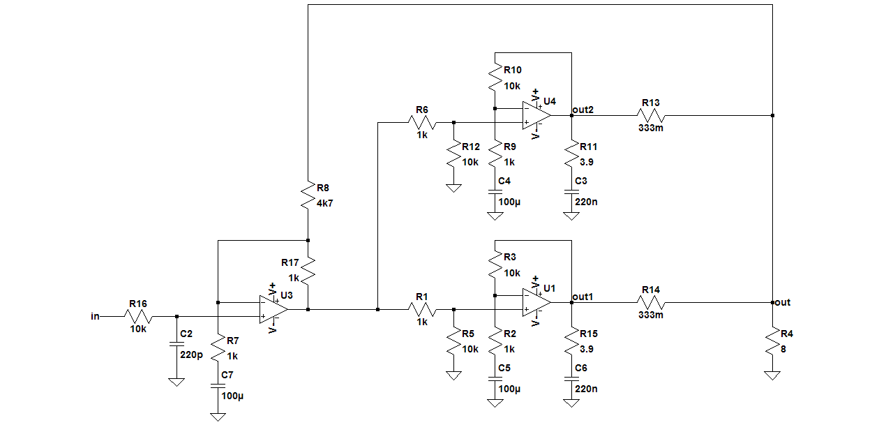
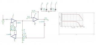
After some fiddling with a couple of parts the circuit seems to be working fine. I had to adjust several things to get the composite part to work. The capacitors C1 and C2 did reduce the oscillations somewhat, but they could not remove them completely. Interestingly I can now remove C1 and C2 completely, as they don't help in any significant way. C1 was replaced by a resistor, which seemingly knocks the open loop gain down and thus makes the whole setup stable. One thing I observed was a peak in the frequency response up above 200kHz which would lead to excessive dissipation when fed with the signal generator, so I added an input filter. With that in place, the frequency response is nice and slowly rolling out, just the way we like it here. Square wave response looks nice and square, with no signs of ringing or overshoot to be seen. Until now I have only tested with +-15V supplies and 4Vpp into 8R load. The opamp I used can take +-20V, so I'll have to find a suitable supply to test the behavior while actually delivering some power.
Attachments

Hi Lasse,
Good work. With the values of R8 and R17 it seems to me that you have little corrective effect from the OP-AMP. Signals at the input will be amplified with 1+R17/R8 = 1.2 so your power stage will have a decent input signal and you have 10 times that signal at the output. The feedback through R8 will reach the input of the power stage with an amplitude of 0.2 of the output amplitude. So, the loop-gain seems very moderate and the correction by the OP-AMP stage little.
Am I right here? If you increase R17 to 100K, does the system then oscillate? Normally, R17 should be (or include) a capacitor for integration effect such that the gain of the OP-AMP at lower frequencies is high and as a result the loop gain becomes high.
I am happy to hear that C4 and C5 are not giving you any problems in the parallel coupling of the two LM1875.
............................................................
With such nice behavior on the scope I bet it already sounds good.
I became curious and decided to put it on my speakers before implementing the OP-AMP.
I connected two 8 Ohm speakers in parallel as it is only a mono test-amplifier. The test-amplifier has shown to be very insensitive to capacitive loading so I skipped the Thiele compensation network and connected to speakers directly on the output of the load balancing resistors.
I used my +/-24V unregulated power supply.
For the quick test, I used church organ music, acoustic guitar music, female vocals, soprano song, bass drum and new age music.
In no situation did I notice any artifacts. The sound level was a above normal listening level.
I am not a trained audiophile listener and I could not detect any flaws.
Turn-on and turn-off was without any "pop" and even with my ear to the speakers, I could detect no hiss or hum.
I will now continue implementing the OP-AMP.
 fine !!
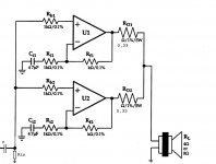
ref. post#464:......see post #406........and in general it follows the bpa100/200 instructions.
later on i will change Rf2 (lowering).
at the output there is a thiele RC network (10 ohm, 47nF).
Rin is 2 x 33k parallel (it is simply a 2 channel stereo amp that i paralleled.....).
later on i will change Rf2 (lowering).
at the output there is a thiele RC network (10 ohm, 47nF).
Rin is 2 x 33k parallel (it is simply a 2 channel stereo amp that i paralleled.....).
Attachments
Last edited:
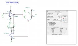
Here is another type of error correction called HAWKSFORD error corrector .
Interesting... I have to study that.
I have not yet implemented the booster transistors to my proto.
But I think I am pretty close eliminating the oscillations!

For those less experienced DIYers who may read this, I will describe a method that goes back before the SmartPhones yikes and even back before Spice-simulation on PCs. The method describes how to stabilize a regulation loop empirically without doing mathematics or simulation. This method has ensured that also your parents had electronics.
Before describing the method, I will just mention a very simple but immensely useful description of an Operational Amplifier (OP-AMP) which is the regulating element in most modern analog systems: An OP-AMP is an electronic circuit that will try to set its output voltage such that the voltage difference between its two inputs becomes zero. A first condition is that the external circuit is made with negative feedback such that the feedback signal will try to reduce (counteract) the effect of the input signal. If the external circuit gives positive feedback, a signal at the input will result in a similar type signal to be added from the feedback and the sum again be amplified until the output saturates - that is not fun for long. Thus, negative feedback. Such a negative feedback loop can only function with a limited regulation bandwidth and if not limited in bandwidth, the regulation loop will oscillate and cause all kinds of unwanted effects. Thus, it is important to adjust the regulation loop such that it becomes stable and does not oscillate.
A second condition is that it is possible for the OP-AMP to achieve zero voltage between the two inputs with the range of its output voltage. This second design-individual criterion will not be discussed here.
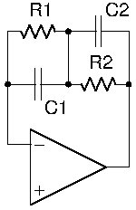
The general feedback circuit looks substantially like the one on the sketch below.
Depending on which characteristic is needed, C1, C2, R1 and R2 are included or a capacitor may be avoided (left open) while a resistor may be replaced by a short-circuit or just removed (left open).
We need precision from our OP-AMP control loop with as high gain as possible in order to minimize the regulation error.
A precision regulation loop is of the integrating type where C1 is of major importance, C2 is avoided, R1 normally can be avoided and R2 is of secondary importance. R1 may be included for a start if DC drift is a problem. If included, R1 should be chosen to a high value like 1 MOhm. R2 should for a start be set to a very low value. Depending on the circuit, C1 should be given a high value for a start (leaving a slow loop), like 10nF. With an oscilloscope at the output, the value of C1 is reduced until oscillation is seen at the output. The value that almost caused oscillation is multiplied by five and that value is used for C1. Then, it is tried if the circuit is still performs well with R1 disconnected. If it still performs well, remove R1. Then R2 is increased in value until oscillation effects are seen at the output. The value of R2 that almost caused oscillation is divided by four and that value is used for R2. Then, another iteration with C1 and subsequently R2 can be performed to make sure that the values are right. This procedure finds values that keep the loop stable and normally also performs quite well. The procedure does not leave absolutely optimized values.
A follow-up analysis by hand calculation (quite some work) or better Spice-simulation is a very good idea. Just remember that the results from a Spice-simulation is no more precise than the Spice-models (mathematical description) used for the components. Luckily, the Spice-models become increasingly precise.
You may also try stability margin test of the circuit with a square-wave signal at the input.
I will try this empiric procedure described above for my OP-AMP loop.
yikes and even back before Spice-simulation on PCs. The method describes how to stabilize a regulation loop empirically without doing mathematics or simulation. This method has ensured that also your parents had electronics.Before describing the method, I will just mention a very simple but immensely useful description of an Operational Amplifier (OP-AMP) which is the regulating element in most modern analog systems: An OP-AMP is an electronic circuit that will try to set its output voltage such that the voltage difference between its two inputs becomes zero. A first condition is that the external circuit is made with negative feedback such that the feedback signal will try to reduce (counteract) the effect of the input signal. If the external circuit gives positive feedback, a signal at the input will result in a similar type signal to be added from the feedback and the sum again be amplified until the output saturates - that is not fun for long. Thus, negative feedback. Such a negative feedback loop can only function with a limited regulation bandwidth and if not limited in bandwidth, the regulation loop will oscillate and cause all kinds of unwanted effects. Thus, it is important to adjust the regulation loop such that it becomes stable and does not oscillate.
A second condition is that it is possible for the OP-AMP to achieve zero voltage between the two inputs with the range of its output voltage. This second design-individual criterion will not be discussed here.
The general feedback circuit looks substantially like the one on the sketch below.
Depending on which characteristic is needed, C1, C2, R1 and R2 are included or a capacitor may be avoided (left open) while a resistor may be replaced by a short-circuit or just removed (left open).
We need precision from our OP-AMP control loop with as high gain as possible in order to minimize the regulation error.
A precision regulation loop is of the integrating type where C1 is of major importance, C2 is avoided, R1 normally can be avoided and R2 is of secondary importance. R1 may be included for a start if DC drift is a problem. If included, R1 should be chosen to a high value like 1 MOhm. R2 should for a start be set to a very low value. Depending on the circuit, C1 should be given a high value for a start (leaving a slow loop), like 10nF. With an oscilloscope at the output, the value of C1 is reduced until oscillation is seen at the output. The value that almost caused oscillation is multiplied by five and that value is used for C1. Then, it is tried if the circuit is still performs well with R1 disconnected. If it still performs well, remove R1. Then R2 is increased in value until oscillation effects are seen at the output. The value of R2 that almost caused oscillation is divided by four and that value is used for R2. Then, another iteration with C1 and subsequently R2 can be performed to make sure that the values are right. This procedure finds values that keep the loop stable and normally also performs quite well. The procedure does not leave absolutely optimized values.
A follow-up analysis by hand calculation (quite some work) or better Spice-simulation is a very good idea. Just remember that the results from a Spice-simulation is no more precise than the Spice-models (mathematical description) used for the components. Luckily, the Spice-models become increasingly precise.
You may also try stability margin test of the circuit with a square-wave signal at the input.
I will try this empiric procedure described above for my OP-AMP loop.
Attachments
Last edited:
Listen to "happy together " by Turtles. The chorus at refrain should not be distorted. MP3 format in YouTube is ok.
I tried it and it seems that my amplifier passed. The chorus part is very strongly modulated and there are some high tones as well. It can easily go wrong. Unfortunately it is from an old analog master tape recorded sometimes in the 60'ties I guess.
Thanks for the tip.
ref. post#464:......see post #406........and in general it follows the bpa100/200 instructions.
later on i will change Rf2 (lowering).
at the output there is a thiele RC network (10 ohm, 47nF).
Rin is 2 x 33k parallel (it is simply a 2 channel stereo amp that i paralleled.....).
Many thanks for the schematic. This way we know what worked and what not. Did you use a single Zobel network after the 0.33 Ohm resistors or two Zobel networks directly on the two amplifier outputs?
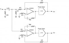
For the OP-AMP controlling loop, I will try to implement the circuit shown below. It is in line with palstanturhin's successful first attempt but using LM4562 instead of NE5534. I go for a gain of 10 for each output such that in BTL coupling, it will be a combined gain of 20.
Attachments
Last edited:
At the moment I have quite good results with this compensation method.
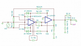
If you get oscillations to the negative channel of the 1875, you may want to try to copy from here... R3,C3,C4.
Value depends on everything else, so cant suggest anything exact. C4 is picofarads. C3 is nanofarads...
But more current should help, so lets see what you get first.
If you get oscillations to the negative channel of the 1875, you may want to try to copy from here... R3,C3,C4.
Value depends on everything else, so cant suggest anything exact. C4 is picofarads. C3 is nanofarads...
But more current should help, so lets see what you get first.
Attachments
- Home
- Amplifiers
- Chip Amps
- LM1875 in parallel configuration and used in a composite amplifier.