Chris and others have put great effort into improving amplifiers based on the LM1875 chip. The results achieved are very promising but evidently limited by the moderate current capability of the LM1875 chip.
In order to overcome the limited current handling of the LM1875, it has been discussed to design a version with more LM1875 operating in parallel such that the current handling is increased. A parallel version may allow for a BTL configured version based on LM1875s with an output power well exceeding 100W. As a last feature, it has been envisaged to use an OP-AMP controlling loop for a composite amplifier design. Composite amplifier designs can achieve very low THD values.
For a start it is foreseen to progress as follows:
a) Discussion of principles and design details, initially of a parallel LM1875 amplifier.
b) Establishment of a design for a parallel LM1875 amplifier.
c) Construction and test of such a parallel LM1875 amplifier.
d) Design of an OP-AMP control loop for the parallel LM1875 amplifier in a composite amplifier configuration.
e) Construction, test and trimming of the composite amplifier.
f) Construction of a similar composite amplifier for a BTL configuration.
g) Test of the composite BTL configured LM1875 amplifier.
h) Eventual PCB layout for those interested.
Anybody is evidently invited to take part, actively or more passively, in this project. It is obviously an objective that the project will end up in a high performance amplifier. But beside that aim, it is hoped that the process will show to less experienced diy’ers what considerations and methods are part of an amplifier design. It should be kept at a level were most members can follow the discussions.
Last edited:
A first issue to discuss is how many LM1875 to put in parallel such that a BTL configuration is possible with the relevant load impedance.
My personal view is that loads between 4 and 8 Ohm are relevant. 2 Ohm loads, I find relate to vehicle use. With 2 Ohm loads, the currents become high while the voltages can remain low such as used for electrical systems in vehicles.
The LM1875 exists from (at least) two sources: The original LM1875 designed and manufactured by National Semiconductor (today TI) and a more recent “CD1875” of Asian origin. The manufacturer of the “CD1875” I cannot identify because I cannot read what I believe to be Chinese. From what I can read in the “CD1875” datasheet , it appears that the specifications are the same for both chips.
From the NS/TI datasheet the following relevant characteristics are found:
Figure 5: Output power vs supply voltage (typical). With a +/-25V supply, the clipping limit with an 8 Ohm load is 25W. 25W in 8 Ohm corresponds to a voltage of 14.1 Vrms or 20 Vpeak. Thus with 25V supply, the chip output will clip at 20V such that the voltage drop caused by the driving circuit is effectively 5V.
With a +/-28V supply, the clipping limit with an 8 Ohm load is 30W. 30W in 8 Ohm corresponds to a voltage of 15.5 Vrms or 22 Vpeak. Thus with 28V supply, the chip output will clip at 22V such that the voltage drop caused by the driving circuit is effectively 6V.
“Description” (page 1) and “Absolute Maximum Ratings” (page 2): The absolute maximum supply voltage is +/-30V (60V total). At the same time, the description indicates that the chip may be used all the way to +/-30V supply. However in order not to exceed the absolute maximum supply voltage, it is risky not to leave a supply voltage margin of 2V such that in reality +/-28V supply is the maximum used. From the section above we know that with +/-28V supply we will (typically) have a clipping voltage of 22V. For SE amplifier configuration, 22V means 2.75Apeak (1.95Arms) in 8 Ohm and 5.5Apeak (3.90Arms) in 4 Ohm. For BTL amplifier configuration (where both voltage and current is doubled), clipping at 22V means 5.5Apeak (3.90Arms) in 8 Ohm and 11Apeak (7.80Arms) in 4 Ohm.
2.75Apeak in 8 Ohm means 30W in 8 Ohm (SE-configuration).
5.5Apeak in 4 Ohm means 60W in 4 Ohm (SE-configuration).
5.5Apeak in 8 Ohm means 120W in 8 Ohm (BTL configuration).
11Apeak in 4 Ohm means 240W in 4 Ohm (BTL configuration).
“Electrical Characteristics, Current Limit” (page 3). The internal current limiter of the LM1875 will typically kick-in at 4A (instant peak) but for sure above 3A (instant peak). Only the limit of 3A can be relied upon in design. The “typical” 4A will provide a convenient margin.
If a good parallel design is made, we can rely on a very good load sharing of the paralleled LM1875.
2.75Apeak can be handled by a single LM1875 to deliver 30W in 8 Ohm. (SE-coupling)
5.5Apeak needs two LM1875 in parallel to deliver 60W in 4 Ohm. (SE-coupling)
5.5Apeak needs two LM1875 in parallel to deliver 120W in 8 Ohm. (BTL coupling)
11Apeak would need four LM1875 in parallel to deliver 240W in 4 Ohm. (BTL coupling)
For a 6 Ohm load, the peak current would be 7.3Apeak in order to deliver 160W in 6 Ohm (BTL coupling). That would require three LM1875 in parallel.
My personal view is that it is exaggerated to design for 240W in 4 Ohm using the guaranteed current limit. With the typical current limit of 4Apeak, the 240W output power in 4 Ohm can be reached with three LM1875 in parallel. Else, the supply voltage can be reduced a little to stay within the guaranteed current limit.
My personal opinion is that three LM1875 in parallel is a good compromise. In BTL coupling, they will allow 120W in 8 Ohm with good current margin or even 160W in 6 Ohm. More than 200W in 4 Ohm may be reached but the supply voltage may instead be reduced such that 160W in 4 Ohm can be reached within guaranteed current limits.
Please let me hear your opinion.
Hi FF
I i read your values i get goosebumps - this will be a power monster.
i would be happy with a 2 parallel chip power amp...
to your description 1 chapter:
look at the note 1:
We should calculate a little less power at 4 R ratings because its written:
1......maximum output power delivered to a 4Ω load may be slightly
reduced when the tab temperature exceeds 55°C.
additionally to that i am not really sure i understand our first discussion about the current limiter in the other thread:
https://www.diyaudio.com/forums/chip-amps/341675-ebay-mono-lm1875-kit-19.html#post5941439
the graph looks like that we are above 20V rail in the current limiter- with 1 chip for sure...? or not?
the page 3 current limiter "formula":
Vout = Vsupply - 10V...4A (typical)--> 3A(tested limit)
Does this mean at this current the Voltage will sag down to Vsupply - 10V??
chris
I i read your values i get goosebumps
- this will be a power monster.i would be happy with a 2 parallel chip power amp...
to your description 1 chapter:
look at the note 1:
We should calculate a little less power at 4 R ratings because its written:
1......maximum output power delivered to a 4Ω load may be slightly
reduced when the tab temperature exceeds 55°C.
additionally to that i am not really sure i understand our first discussion about the current limiter in the other thread:
https://www.diyaudio.com/forums/chip-amps/341675-ebay-mono-lm1875-kit-19.html#post5941439
the graph looks like that we are above 20V rail in the current limiter- with 1 chip for sure...? or not?
the page 3 current limiter "formula":
Vout = Vsupply - 10V...4A (typical)--> 3A(tested limit)
Does this mean at this current the Voltage will sag down to Vsupply - 10V??
chris
Attachments
Will the amps paralleled as low impedance voltage or high impedance current (Holloway)? If the finality is BTL, I suggest to be single supply to allow use of a standard 48v switching power supply.
Hi
Why you are thinking about single supply voltage at that chip?
chris

Hi Chris,
I i read your values i get goosebumps - this will be a power monster.
i would be happy with a 2 parallel chip power amp...
Two parallel LM1875 will be sufficient for much. It is easy to choose two, three or or even four LM1875 in parallel because each LM1875 block will be similar with the other and only the load sharing resistors may need to be adapted to the number of LM1875 in parallel.
Personally, I may implement a three LM1875 power amplifier while other can choose for their personal needs. With three LM1875 in parallel, I will have higher current margins than with only two but else the power amplifier behavior will be very similar (gain, THD etc.)
to your description 1 chapter:
look at the note 1:
We should calculate a little less power at 4 R ratings because its written:
1......maximum output power delivered to a 4Ω load may be slightly
reduced when the tab temperature exceeds 55°C.
My first reaction is that a heatsink should be less than 55 degrees warm. As also indicated in the NS/TI datasheet, the LM1875 is a bit (current-) marginal for 4 Ohm loads. The datasheet proposes to reduce the supply voltage in order to compensate for the higher currents in 4 Ohm. By putting more LM1875 in parallel, we generally said make the load impedance seen by each LM1875 chip higher. Two LM1875 in parallel make a 4 Ohm load look like an 8 Ohm load for each LM1875 chip, roughly seen. With three LM1875 in parallel, a 4 Ohm load will look like a 12 Ohm load etc. Thus, the datasheet concerns for use of 4 Ohm loads are circumvented by more LM1875 put in parallel.
additionally to that i am not really sure i understand our first discussion about the current limiter in the other thread:
https://www.diyaudio.com/forums/chip-amps/341675-ebay-mono-lm1875-kit-19.html#post5941439
the graph looks like that we are above 20V rail in the current limiter- with 1 chip for sure...? or not?
the page 3 current limiter "formula":
Vout = Vsupply - 10V...4A (typical)--> 3A(tested limit)
Does this mean at this current the Voltage will sag down to Vsupply – 10V??
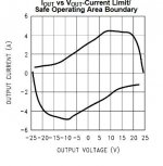
It seems that in my posting #187 I have grossly dodged your question about how to interpret the two graphs. I hate strange looking graphs in datasheets but now I had to concentrate and think.
To me, the two graphs look like two graphs describing the dynamic value of the positive and negative chip current limiters respectively. The chip is supposed to operate in-between the to curves.
I will try to explain: Had the current limiter values been for instance 3A fixed, the curves would have been two horizontal lines at +3A and -3A. The LM1875 has a (typical) dynamic characteristic such that at an output voltage of 0V, 3A can be drawn before the current limiter is activated, at 5V output voltage 4A, at 10V-15V output voltage more than 4A, at 20V output voltage 4A. Above 20V output voltage the current limit drops very rapidly. Similarly for the negative current limiter.
With a constant value load at the output, the current in the load increases steadily and linearly from zero. As long as the load current curve stays below the dynamic current limit curve, there is no problem. Above an output voltage of 20V, the load current curve is close to the dynamic current limit curve and problems start. It appears prudent to avoid operating in the area with output voltages above 20V where the current limit drops very rapidly. The supply voltage should be limited to +/-25V such as concluded from Figure 5 of the datasheet.
If we limit the supply voltage to +/-25V such that we can expect output signal clipping at 20V, the output power calculations become:
SE-coupling: 25W in 8 Ohm.
SE-coupling: 50W in 4 Ohm.
BTL-coupling: 100W in 8 Ohm.
BTL-coupling: 133W in 6 Ohm.
BTL-coupling: 200W in 4 Ohm.
Still respectable values.
I i read your values i get goosebumps - this will be a power monster.
i would be happy with a 2 parallel chip power amp...
Two parallel LM1875 will be sufficient for much. It is easy to choose two, three or or even four LM1875 in parallel because each LM1875 block will be similar with the other and only the load sharing resistors may need to be adapted to the number of LM1875 in parallel.
Personally, I may implement a three LM1875 power amplifier while other can choose for their personal needs. With three LM1875 in parallel, I will have higher current margins than with only two but else the power amplifier behavior will be very similar (gain, THD etc.)
to your description 1 chapter:
look at the note 1:
We should calculate a little less power at 4 R ratings because its written:
1......maximum output power delivered to a 4Ω load may be slightly
reduced when the tab temperature exceeds 55°C.
My first reaction is that a heatsink should be less than 55 degrees warm. As also indicated in the NS/TI datasheet, the LM1875 is a bit (current-) marginal for 4 Ohm loads. The datasheet proposes to reduce the supply voltage in order to compensate for the higher currents in 4 Ohm. By putting more LM1875 in parallel, we generally said make the load impedance seen by each LM1875 chip higher. Two LM1875 in parallel make a 4 Ohm load look like an 8 Ohm load for each LM1875 chip, roughly seen. With three LM1875 in parallel, a 4 Ohm load will look like a 12 Ohm load etc. Thus, the datasheet concerns for use of 4 Ohm loads are circumvented by more LM1875 put in parallel.
additionally to that i am not really sure i understand our first discussion about the current limiter in the other thread:
https://www.diyaudio.com/forums/chip-amps/341675-ebay-mono-lm1875-kit-19.html#post5941439
the graph looks like that we are above 20V rail in the current limiter- with 1 chip for sure...? or not?
the page 3 current limiter "formula":
Vout = Vsupply - 10V...4A (typical)--> 3A(tested limit)
Does this mean at this current the Voltage will sag down to Vsupply – 10V??
It seems that in my posting #187 I have grossly dodged your question about how to interpret the two graphs. I hate strange looking graphs in datasheets but now I had to concentrate and think.
To me, the two graphs look like two graphs describing the dynamic value of the positive and negative chip current limiters respectively. The chip is supposed to operate in-between the to curves.
I will try to explain: Had the current limiter values been for instance 3A fixed, the curves would have been two horizontal lines at +3A and -3A. The LM1875 has a (typical) dynamic characteristic such that at an output voltage of 0V, 3A can be drawn before the current limiter is activated, at 5V output voltage 4A, at 10V-15V output voltage more than 4A, at 20V output voltage 4A. Above 20V output voltage the current limit drops very rapidly. Similarly for the negative current limiter.
With a constant value load at the output, the current in the load increases steadily and linearly from zero. As long as the load current curve stays below the dynamic current limit curve, there is no problem. Above an output voltage of 20V, the load current curve is close to the dynamic current limit curve and problems start. It appears prudent to avoid operating in the area with output voltages above 20V where the current limit drops very rapidly. The supply voltage should be limited to +/-25V such as concluded from Figure 5 of the datasheet.
If we limit the supply voltage to +/-25V such that we can expect output signal clipping at 20V, the output power calculations become:
SE-coupling: 25W in 8 Ohm.
SE-coupling: 50W in 4 Ohm.
BTL-coupling: 100W in 8 Ohm.
BTL-coupling: 133W in 6 Ohm.
BTL-coupling: 200W in 4 Ohm.
Still respectable values.
I fully agree with kokoriantz that a single supply version is more convenient in the end and that 48V supply is very suited.
During the initial design and test I would prefer the symmetrical power supply with a "real" ground line as reference.
The two first parts are test of SE-configurations which is easier with a real return line. Offset voltages for each LM1875 block will have to be trimmed out which is easier with reference to a real ground line.
With a single supply voltage, we will have to create a virtual signal reference line. Most BTL chips like those for car audio and class D have a virtual signal line integrated in the chip such that we only need to couple the signal to the input with a capacitor. Such BTL chips take care of the rest. The LM1875 has no such integrated feature and we will have to design it ourselves. If we have self-oscillation problems or hum, the virtual reference design may be suspected as being a part of the reason.
A single supply version I find is a good idea when the BTL version using a symmetrical supply works well such that it is the virtual signal reference we can concentrate on.
The LM1875 I will be using are bought for around 2 Eur per 10 pcs. Probably "fake" or CD1875 versions but I have already tested two items and they seem to work. At least when I do not take them to the limit.
Last edited:
Hi Chris,
I i read your values i get goosebumps - this will be a power monster.
i would be happy with a 2 parallel chip power amp...
Two parallel LM1875 will be sufficient for much. It is easy to choose two, three or or even four LM1875 in parallel because each LM1875 block will be similar with the other and only the load sharing resistors may need to be adapted to the number of LM1875 in parallel.
Personally, I may implement a three LM1875 power amplifier while other can choose for their personal needs. With three LM1875 in parallel, I will have higher current margins than with only two but else the power amplifier behavior will be very similar (gain, THD etc.)
to your description 1 chapter:
look at the note 1:
We should calculate a little less power at 4 R ratings because its written:
1......maximum output power delivered to a 4Ω load may be slightly
reduced when the tab temperature exceeds 55°C.
My first reaction is that a heatsink should be less than 55 degrees warm. As also indicated in the NS/TI datasheet, the LM1875 is a bit (current-) marginal for 4 Ohm loads. The datasheet proposes to reduce the supply voltage in order to compensate for the higher currents in 4 Ohm. By putting more LM1875 in parallel, we generally said make the load impedance seen by each LM1875 chip higher. Two LM1875 in parallel make a 4 Ohm load look like an 8 Ohm load for each LM1875 chip, roughly seen. With three LM1875 in parallel, a 4 Ohm load will look like a 12 Ohm load etc. Thus, the datasheet concerns for use of 4 Ohm loads are circumvented by more LM1875 put in parallel.
additionally to that i am not really sure i understand our first discussion about the current limiter in the other thread:
https://www.diyaudio.com/forums/chip-amps/341675-ebay-mono-lm1875-kit-19.html#post5941439
the graph looks like that we are above 20V rail in the current limiter- with 1 chip for sure...? or not?
the page 3 current limiter "formula":
Vout = Vsupply - 10V...4A (typical)--> 3A(tested limit)
Does this mean at this current the Voltage will sag down to Vsupply – 10V??
It seems that in my posting #187 I have grossly dodged your question about how to interpret the two graphs. I hate strange looking graphs in datasheets but now I had to concentrate and think.
To me, the two graphs look like two graphs describing the dynamic value of the positive and negative chip current limiters respectively. The chip is supposed to operate in-between the to curves.
I will try to explain: Had the current limiter values been for instance 3A fixed, the curves would have been two horizontal lines at +3A and -3A. The LM1875 has a (typical) dynamic characteristic such that at an output voltage of 0V, 3A can be drawn before the current limiter is activated, at 5V output voltage 4A, at 10V-15V output voltage more than 4A, at 20V output voltage 4A. Above 20V output voltage the current limit drops very rapidly. Similarly for the negative current limiter.
With a constant value load at the output, the current in the load increases steadily and linearly from zero. As long as the load current curve stays below the dynamic current limit curve, there is no problem. Above an output voltage of 20V, the load current curve is close to the dynamic current limit curve and problems start. It appears prudent to avoid operating in the area with output voltages above 20V where the current limit drops very rapidly. The supply voltage should be limited to +/-25V such as concluded from Figure 5 of the datasheet.
If we limit the supply voltage to +/-25V such that we can expect output signal clipping at 20V, the output power calculations become:
SE-coupling: 25W in 8 Ohm.
SE-coupling: 50W in 4 Ohm.
BTL-coupling: 100W in 8 Ohm.
BTL-coupling: 133W in 6 Ohm.
BTL-coupling: 200W in 4 Ohm.
Still respectable values.
Hi FF,
first i do not want to finish with 2 parallel chips - it was just an idea.
Thanks FF for explanation that is what i mean. so 25VDC = is about 18VAC?
in real i had the 18VAC and in idle i got about 26,3VDC
or should we use a 15VAC?....15VAC * 1,5 = 22,5VDC
chris
Which one to your opinion to choose?
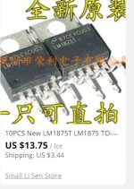
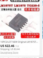
Sorry kokoriantz...I will not support a possible fake chip manufactor.
i us eht origin 1875 by TI store
The problem with IC amps is the lead thickness. The American wire table which is religiously respected by transformer, capacitor manufacturers shows the maximum current the wire can be used for power transmission. The nonmagnetic leads of LM1875 as 3886 are equivalent to 0.64mm thick wire , the table shows 0.95A max can be transmitted. If 8 ohms load is used ,max power is 3.6W. This why the bass notes being higher in power gets dried out. Paralleling resolves this problem.I honestly don't see much point in 2 paralleled 1875. One lm3886 is just as powerful. With 3 or more, things get interesting as you can maybe better spread heat around.
The LM1875 is over 20years old by this the patents are in public domain . Similarly you don't buy BD139/140 from Telefunken but a copy of it , The generic versions are ok , but what goes wrong is to get a fake un operating one or original but factory rejects.
voltage or current Holloway? If voltage , how many ohms to be the joining resistor? Can you post a picture of your 1875 ?
Load sharing resistors to be discussed. I guess 0.33 Ohm or 0.5 Ohm.
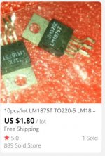
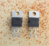
It seems I paid around 3 Eur for 10 pcs. Photo appended.
Attachments
It looks similar to this . The shipment cost is for Thailand, the same for 10 pieces.Load sharing resistors to be discussed. I guess 0.33 Ohm or 0.5 Ohm.
It seems I paid around 3 Eur for 10 pcs. Photo appended.
I suppose you optioned for voltage .
Attachments
Last edited:
Sorry but that's just nonsense. The 0.95A max is for power transmission. Rating for chassis rating is already at 7A and even that doesn't apply to such short leads in open air. TI engineers will have determined the proper sizing of the leads based on temp raise and voltage drop.The problem with IC amps is the lead thickness. The American wire table which is religiously respected by transformer, capacitor manufacturers shows the maximum current the wire can be used for power transmission. The nonmagnetic leads of LM1875 as 3886 are equivalent to 0.64mm thick wire , the table shows 0.95A max can be transmitted. If 8 ohms load is used ,max power is 3.6W. This why the bass notes being higher in power gets dried out. Paralleling resolves this problem.
PS: Eventual problems with low notes at high power come from the SPIKE protection system with the lm3886.
I honestly don't see much point in 2 paralleled 1875. One lm3886 is just as powerful. With 3 or more, things get interesting as you can maybe better spread heat around.
You are right in that this LM1875 project is not about how to make a composite amplifier in the most rational way. Had it been, we would have used LM3886 or TDA7293. Your level of skills has been noticed and this project will hardly teach you anything.
We are a number of persons having LM1875 (more or less genuine) in stock or the option to buy LM1875 at a good price. The aim is to show how such simple but well performing chips can be arranged in parallel to compensate for their moderate current capability and allow BTL use. On top of that, use in a composite amplifier configuration will bring down the THD and allow feedback from after the load sharing resistors. I am convinced we will reach a good result but we will neither take away the interest for the Fremen design, nor put Neurochrome out of business. Due to only 5 pins, the LM1875 is easy to use in a Vero-board. Further, as you already point out, the heat losses will be spread out.
- Home
- Amplifiers
- Chip Amps
- LM1875 in parallel configuration and used in a composite amplifier.