.. and even then, there is the the LM1876
Was it to put only two in parallel, the LM1876 could be used. Very good chip. However, we have a lot of LM1875 in stock.......
You are right in that this LM1875 project is not about how to make a composite amplifier in the most rational way. Had it been, we would have used LM3886 or TDA7293. Your level of skills has been noticed and this project will hardly teach you anything.
We are a number of persons having LM1875 (more or less genuine) in stock or the option to buy LM1875 at a good price. The aim is to show how such simple but well performing chips can be arranged in parallel to compensate for their moderate current capability and allow BTL use. On top of that, use in a composite amplifier configuration will bring down the THD and allow feedback from after the load sharing resistors. I am convinced we will reach a good result but we will neither take away the interest for the Fremen design, nor put Neurochrome out of business. Due to only 5 pins, the LM1875 is easy to use in a Vero-board. Further, as you already point out, the heat losses will be spread out.
Yes 00940... i read a lot and with this "project" you will not learn much by me
") yes FF we try the LM1875- i 100% agree with your comments.
yes FF we try the LM1875- i 100% agree with your comments.chris
....current test with 1 LM1875 at 4,459R...
Hi
to be clear which supply voltage we should have for 4 R load i did a test again.
to get 3Amps aout we need at 4,459R a Voltage rms about 13,37V at the resistor.
i use 25V supply but with the with 450mVrms i get this current limiter. switch on_off_ on off --> i show this in the LM1875 kit thread.
i go dwon with the supply 20V - this is the max off Voltage of the chip to do not go into the limiter. and here are the results:
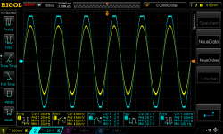
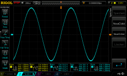
pic 1 +/- 20V supply 500mVrms in (G=27dB) 11,2 Vrms at the load of 4,459R -- clipping
pic 2 +/- 20V supply 480mVrms in (G=27dB) 10,6 Vrms at the load of 4,459R -- clipping
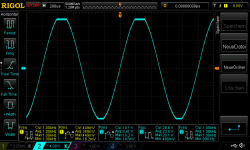
pic 3 +/- 20V supply 460mVrms in (G=27dB) 10,2 Vrms at the load of 4,459R -- no clipping - this give us a current of 2,287Amps continuous
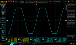
pic 4 +/- 15V supply 460mVrms in (G=27dB) 9,3 Vrms at the load of 4,459R -- clipping - supply voltage too low
pic 5 +/- 18V supply 460mVrms in (G=27dB) 10,1 Vrms at the load of 4,459R -- clipping - supply voltage too low - closed to 20V supply but not enough this give us a current of 2,265Amps continuous
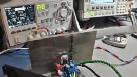
pic 6 is the test enviroment - idle - no signal
so we should calculate per chip at 4R with 2,2 continuous?
chris
Hi
to be clear which supply voltage we should have for 4 R load i did a test again.
to get 3Amps aout we need at 4,459R a Voltage rms about 13,37V at the resistor.
i use 25V supply but with the with 450mVrms i get this current limiter. switch on_off_ on off --> i show this in the LM1875 kit thread.
i go dwon with the supply 20V - this is the max off Voltage of the chip to do not go into the limiter. and here are the results:
pic 1 +/- 20V supply 500mVrms in (G=27dB) 11,2 Vrms at the load of 4,459R -- clipping
pic 2 +/- 20V supply 480mVrms in (G=27dB) 10,6 Vrms at the load of 4,459R -- clipping
pic 3 +/- 20V supply 460mVrms in (G=27dB) 10,2 Vrms at the load of 4,459R -- no clipping - this give us a current of 2,287Amps continuous
pic 4 +/- 15V supply 460mVrms in (G=27dB) 9,3 Vrms at the load of 4,459R -- clipping - supply voltage too low
pic 5 +/- 18V supply 460mVrms in (G=27dB) 10,1 Vrms at the load of 4,459R -- clipping - supply voltage too low - closed to 20V supply but not enough this give us a current of 2,265Amps continuous
pic 6 is the test enviroment - idle - no signal
so we should calculate per chip at 4R with 2,2 continuous?
chris
Attachments
-
 20V supply 500mVrms in at 4,459R_clipping.png57.6 KB · Views: 722
 -
 current test with 20V supply at 4,45R.jpg144.2 KB · Views: 261
 -
 18V supply 460mVrms in at 4,459R_clipping.png46.6 KB · Views: 710
 -
 15V supply 460mVrms in at 4,459R_clipping.png45.3 KB · Views: 698
 -
 20V supply 460mVrms in at 4,459R_no clipping.png47 KB · Views: 708
 -
 20V supply 480mVrms in at 4,459R_clipping.png46.9 KB · Views: 716
Last edited:
Good work as usual, Chris. The current limit kicks in at 2.3Arms corresponding to 3.25Apeak. I assumed use to 3Apeak in the initial estimations so that wasn't completely wrong.
Was this an Amazon chip or a genuine TI chip?
FF i will never say/write that you made a mistake....
if i did no mistake at my workbench....
original TI chip...to confirm this test i will do this test with my amp boards = amp 1_2 the nichicon UES board....
Hi FF
according to post 9
If we limit the supply voltage to +/-25V such that we can expect output signal clipping at 20V, the output power calculations become:
SE-coupling: 25W in 8 Ohm.
SE-coupling: 50W in 4 Ohm.
BTL-coupling: 100W in 8 Ohm.
BTL-coupling: 133W in 6 Ohm.
BTL-coupling: 200W in 4 Ohm.
Still respectable values.
what about the Transformer ratings?
2x15VAC - 160VA-200VA -230VA for both channels
chris
Attachments

7A chassis is valid if the wires have their magnetic field constrained by a steel chassis or the leads are magnetic as the case for electrolytic capacitors and was with metal case transistors.Sorry but that's just nonsense. The 0.95A max is for power transmission. Rating for chassis rating is already at 7A and even that doesn't apply to such short leads in open air. TI engineers will have determined the proper sizing of the leads based on temp raise and voltage drop.
PS: Eventual problems with low notes at high power come from the SPIKE protection system with the lm3886.
7A chassis is valid if the wires have their magnetic field constrained by a steel chassis or the leads are magnetic as the case for electrolytic capacitors and was with metal case transistors.
Sorry for continuing the OT but those ratings have nothing to do with magnetic fields, they're just a matter of overheating. The power transmission rating is constrained by the fact that the wires can be run bundled while the chassis rating depends on a single wire that can run hotter.
Do you have a source to back what you're saying ?
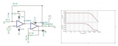
here is a first approach for composite .
I agree on the design. We may have to adapt some component values. With the present values, the gain of the LM1875 should be below the minimum gain for stability (10 times / 20dB).
Hi FF
according to post 9
If we limit the supply voltage to +/-25V such that we can expect output signal clipping at 20V, the output power calculations become:
SE-coupling: 25W in 8 Ohm.
SE-coupling: 50W in 4 Ohm.
BTL-coupling: 100W in 8 Ohm.
BTL-coupling: 133W in 6 Ohm.
BTL-coupling: 200W in 4 Ohm.
Still respectable values.
what about the Transformer ratings?
2x15VAC - 160VA-200VA -230VA for both channels
chris
I would rather use 2x18Vac. Rectified and idle that would be 2x27Vdc but loaded the voltage will drop to around 2x25Vdc.
2x17Vac is unfortunately not standard.
2x15Vac rectified and idle would be 2x23Vdc but dropping to 2x20Vdc when loaded. Too low I find.
230VA seems right for two channels.
NB: I have variable (linear) voltage regulators covering that voltage range but hardly transformer power to test two channels simultaneously. I will make a mono version so I can test it in full.
Look at the frequency response curve/ phase , there is no any resonance. The LM3886 also is 20db minimum but with 1K input impedance, I use it at gain 10db stand alone with 100 ohms impedance without any problem . On simulator it shows the same behavior with 1875. The AD8008 is a CFA with open loop frequency response of 100khz , the open loop gain is adjusted by the negative input resistance 1K bringing the open loop gain of about 70db. With closed loop gain of 20db, and 10db gain of LM1875, it provides 40db enhancement . Of course the distortion now is dependent mainly to the op amp. Simulator calculates 0.00025% @10khz.I agree on the design. We may have to adapt some component values. With the present values, the gain of the LM1875 should be below the minimum gain for stability (10 times / 20dB).
Last edited:
The one who discovered this phenomena invented the fuse . Thomas Edison. It was known beforehand for telegraph wire protection from lightning, that a wire of 0.1mm what ever is the length gets destroyed at 3A. An old British wire table shows. By using fused metal instead of uniform wire , Edison could make the nonlinear character of the Conductance more sudden.Sorry for continuing the OT but those ratings have nothing to do with magnetic fields, they're just a matter of overheating. The power transmission rating is constrained by the fact that the wires can be run bundled while the chassis rating depends on a single wire that can run hotter.
Do you have a source to back what you're saying ?
Ask yourself the question, why electrolytic, ceramic, high quality capacitors have magnetic leads.
This subject is known by electrical engineers but not by electronics . My son ,MSEE, PhD physics has never heard of it .
Last edited:
...American wire table which is religiously respected by transformer, capacitor manufacturers shows the maximum current the wire can be used for power transmission. The nonmagnetic leads of LM1875 as 3886 are equivalent to 0.64mm thick wire , the table shows 0.95A max can be transmitted.
I don't know how 'religious' it gets. Ampacity depends a LOT on conditions, and is more often limited by connectors than the wire itself. In house-wiring I have to assume 60C max because some cheap outlets get saggy when that hot. The chip is made for heat and good PCB will stand heat also.
0.64mm diameter seems to be AWG #22, which is good for 3 to 5 Amps at 90 deg C all day and all night.
https://www.gore.com/IndustrialCableConfigurator/popup_hfr_wirespecs.html
AWG Wire Gauges Current Ratings
...bass notes being higher in power gets dried out. ...
OK
So we're now talking fusing rating. Which is a different thing. For a copper 22awg wire (similar to the lm3886 leads), it's 41A. For iron, only 13A. And once again, it's a heat problem: (PDF) Fusing of wires by electrical currentThe one who discovered this phenomena invented the fuse . Thomas Edison. It was known beforehand for telegraph wire protection from lightning, that a wire of 0.1mm what ever is the length gets destroyed at 3A. An old British wire table shows. By using fused metal instead of uniform wire , Edison could make the nonlinear character of the Conductance more sudden.
Ask yourself the question, why electrolytic, ceramic, high quality capacitors have magnetic leads.
If the lm3886/lm1875 leads weren't able to carry the needed current, it would be trivial to measure and the leads would fail due to repeated stress... obviously that doesn't happen.
As far as I know, caps have magnetic leads because of manufacturing reasons (strength of leads notably) and costs. And plenty of caps have non magnetic leads: THE non-magnetic parts list
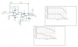
With this version you can adjust the open loop frequency response vs NFB , by adjusting R1 &C1. It allows you to tune by ears for best sound . Chermann , as you have a working circuit on bench , can you please replace the feedback resistors to 180 ohms 1W /100 ohms and listen the sound using multiple brass jazz orchestras.
Attachments
Last edited:
If you need to design a transformer by traditional way described in Radiotron , you are asked to look at American Wire table to know the thickness of wire for the current rms it carries. I couldn't find out why the rms and not the peak. The temperature depends off course from the resistance . If too hot than a bigger size magnetics is necessary to have shorter length.I don't know how 'religious' it gets. Ampacity depends a LOT on conditions, and is more often limited by connectors than the wire itself. In house-wiring I have to assume 60C max because some cheap outlets get saggy when that hot. The chip is made for heat and good PCB will stand heat also.
0.64mm diameter seems to be AWG #22, which is good for 3 to 5 Amps at 90 deg C all day and all night.
https://www.gore.com/IndustrialCableConfigurator/popup_hfr_wirespecs.html
AWG Wire Gauges Current Ratings
OK
- Home
- Amplifiers
- Chip Amps
- LM1875 in parallel configuration and used in a composite amplifier.