I would like to ask how I should connect the input electrolytic capacitor to LM3886 IC. Searching online did not result in any finds whatsoever. Only one schematic had a properly marked input capacitor. Since an electrolytic capacitor is polarised, I would like to know how this should be connected to the input. The IC's non-inverting input is connected to a resistor chain of two series resistors. The resistor that directly connects to the chip is 1k and the other , 22k, connects to ground. Signals will be fed at the point between these resistors. Which capacitor's electrode should be connected to this point? The input signal will be applied between the capacitor's other terminal and ground.
Last edited:
Electrolytic capacitors are also built and sold, in "non polar" (sometimes called "bi polar") configurations. These capacitors are not polarized; their leads are not marked "+" and "-"; you can connect them either way and they'll still work. Here is how to find them on mouser.com (attached image). For your chipamp, you might want to consider the Nichicon "Bi Polar" capacitor series called UES. To name one example, the Nichicon UES 22uF, 50 volt capacitor is Mouser part number 647-UES1H220MPM and its price is less than one dollar.
_
_
Attachments

Check the LM3886 pdf data sheet equivalent circuit and you will see that the input transistors are NPN. This means that they draw current towards the negative rail so the + and - inputs have a slight negative DC voltage wrt ground. So you need to wire the caps with the negative side towards the chip, assuming you are building a dual voltage supply. If you are building a single supply amp then the inputs are biased at half the supply voltage and positive assuming the negative rail is ground. That includes both the input coupling caps and the feedback de-coupling caps. When you have it up and running, you can verify this by measuring the small voltage on these pins.
Last edited:
I would like to ask...
Why do you ask a question in one thread then start another thread to ask the same question?
What to do about mismatched IC footprints?
Check the LM3886 pdf data sheet equivalent circuit and you will see that the input transistors are NPN. This means that they draw current towards the negative rail so the + and - inputs have a slight negative DC voltage wrt ground. So you need to wire the caps with the negative side towards the chip, assuming you are building a dual voltage supply. If you are building a single supply amp then the inputs are biased at half the supply voltage and positive assuming the negative rail is ground. That includes both the input coupling caps and the feedback de-coupling caps. When you have it up and running, you can verify this by measuring the small voltage on these pins.
Thanks, you corroborate my observations.
Regarding using a non-polarized electrolytic capacitor at the input, I think, this is usually not done. I only encountered such capacitors as speaker filters where they are a necessity. At an amplifier input, the voltage variation on an electrolytic capacitor should be very very small. This means, there is no restricting necessity to use bi-polar capacitors.
P.S.
I have two ~2cm ferrite toroids that I am thinking about using as output filter inductors. I will wind a few turns until the inductance is 0.7uH. A few turns will mean the core will never saturate.
Last edited:
The problem with Mouser is I found it has a prohibitively expensive mail. There are other mail options available to the default option, but, the cost is not given during the order, and one has to pay on arrival of items. The default mail option was about €20 for just a few grams of mail!Mark Johnson said:To name one example, the Nichicon UES 22uF, 50 volt capacitor is Mouser part number 647-UES1H220MPM and its price is less than one dollar.
I wish I am doing something wrong in my orders, but till now, I am always getting very expensive costings which discourage me from placing orders.
Hello,
The first post from Edbarx in this thread makes me arise a question:
The only way to arrange the input network that makes really sense to me, is exactly the way described in this post. Namely, version 1 in the picture I attached.
The problem is, that in some boards available on the market (especially ebay, I won't name them) the input is like in version 2 , except by the fact that capacitor C6 between the opamp's inputs pins is usually not present, but that capacitor is an unrelated topic, i suppose.
Placing the resistors like in version 2 (i mean moving R9), if i am not mistaken, should decrease the gain and increase the offset. Then, does anybody have any idea why some PCBs have an input network done like that? Am I missing something?
Thank you in advance for any suggestion,
Cheers!
Attachments
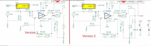
The problem with circuit #1 is that he resistance from +in to ground is 23K and between -in and output is 22k, which will create a slight offset equal to 1K times the input bias current. For #2, both are 22k, ie they match and should cancel each other, minimal offset. The gain for #1 is 22/23*23/1 = 22. The gain for #2 is 23/1, a difference of 0.2dB.
If you are using split supplies put + on cap to input.
If you are using unipolar supply put - on cap to input.
Or, put two electrolytics back to back and they can go either way around.
Or, use unipolar cap.
An polarised electrolytic will stand up to 1V5 reverse voltage before becoming a short.
If you are using unipolar supply put - on cap to input.
Or, put two electrolytics back to back and they can go either way around.
Or, use unipolar cap.
An polarised electrolytic will stand up to 1V5 reverse voltage before becoming a short.
Steveu, you made me realize that I made a silly mistake in both circuits! I forgot the >=100uF capacitor between R5 and VCM, and I didn't see the 1kohm path from the inverting input to ground that requires the introduction of that cap. Sorry for the confusion, sometimes i am selectively blind!
Now i see that circuit #2 with that cap, has less offset. But still i see a gain decrease: in #2, R9 and R8 make a resistive partition of the input voltage, then in that case the gain should be 22/23*23, not in #1.
Aside from the minimal offset introduced (that can be addressed by chosing R8+R9=R4), are there any drawbacks in positioning R9 like in #1?
Ya, I didn't notice that cap was missing either, otherwise the -in is <1K from VCM, which would create offset problems. Some do this deliberately for DC response and tweak the offset to compensate.
Using two resistors for R4 (=R8+R9) is the easiest way, but the difference between 23K and 22K may not be enough offset to worry about. But 0.2dB attenuation is not a big problem either. If you are using chip-amps then such fine points are over design.
Using two resistors for R4 (=R8+R9) is the easiest way, but the difference between 23K and 22K may not be enough offset to worry about. But 0.2dB attenuation is not a big problem either. If you are using chip-amps then such fine points are over design.
Last edited:
You convinced me, i am overthinking it!
Then I also understood that the network which attenuates the input is a good solution when offset, cost and compactness are taken very serously: that strategy doesn't require resistors of non-standard values. I found it surprising but, when available, they may cost something like 0.35 euro each on mouser and similar distributors.
Then I also understood that the network which attenuates the input is a good solution when offset, cost and compactness are taken very serously: that strategy doesn't require resistors of non-standard values. I found it surprising but, when available, they may cost something like 0.35 euro each on mouser and similar distributors.
- Status
- This old topic is closed. If you want to reopen this topic, contact a moderator using the "Report Post" button.
- Home
- Amplifiers
- Chip Amps
- Input to LM3886.