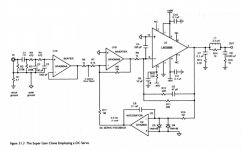
In his book Designing Audio Power Amplifiers (2nd edition), Bob Cordell discusses a chipamp he designed around the National Semiconductor LM3886. Bob calls it the Super Gain Clone, and he summarizes its features as follows:
I contacted Bob and received permission to create a PCB of the Super Gain Clone, for members of diyAudio. The schematic of my PCB, which is merely a straightforward copy of the schematic in Bob's book, is shown in Figure 1 below. Figure 2 is a photo of the board, stuffed and soldered and mounted to the heatsink of a diyAudio Store "Dissipante 2U" chassis. The complete stereo amplifier is shown in Figure 3. It fits nicely and looks quite sharp in the not-very-tall (88 mm) 2U chassis. I used the Dissipante with the smallest available depth (300 mm).
And then a second PCB, for people who want a much smaller amp-channel board, was created. This board began as a copy of the Super Gain Clone board layout, but then discarded several pieces of circuitry. I amputated the inverting input buffer, the DC servo, and the Klever Klipper subcircuits; the resulting small board is called "Compact3886". Its schematic is shown in Figure 4. Figure 5 is a photo of a populated Compact3886 board, and Figure 6 is a complete stereo amplifier using two Compact3886 amp boards.
MOUNTING TO THE HEATSINK
Unlike the PCBoards which follow the diyAudio Universal Mounting Specification ("UMS"), the Super Gain Clone PCB and the Compact3886 PCB are mounted perpendicular to the heatsink. So they are certainly not compatible with UMS. You will have to drill and tap three holes for each amp PCB; one hole to bolt the LM3886 to the heatsink, and two more holes to bolt the PCB support L-Brackets to the heatsink. A drilling template is provided in the pdf documentation.
In fact, drilling and tapping your own holes is inevitable, because the very slick-looking 2U chassis in the Store are only available with undrilled and untapped heatsinks. (2U is not tall enough to accomodate the UMS footprint). Luckily, 3 holes is not a large number to drill and tap, even for a beginner. And remember, if you make a mistake, you can slide the template 10mm left or right and try again. The PCBs are short while the heatsinks are long. The "extra" holes will be inside the chassis and invisible to onlookers.
WHAT POWER TRANSFORMER WILL YOU NEED?
You'll need a power transformer rated at least 200 volt-amperes ("VA"), with dual independent secondaries, and with primaries that are compatible with the AC mains in your country. Using the rule of thumb
DC_supply_voltage =approx= [(Trafo secondary rating in VAC rms) * 1.414] - 3.1V,
and consulting the LM3886 datasheet's Absolute Maximum Ratings, I conclude that you can use any 200VA transformer you like, as long as its secondary's output voltage is between 14.5VAC and 31.5VAC (rms ratings at full load). The LM3886 datasheet provides a helpful graph that I have copied below as Figure 7. Applying the above rule of thumb, we get Figure 8. These predict the maximum output power at the onset of clipping (namely, when THD rises to 0.1%).
WHICH SPECIFIC POWER TRANSFORMER IS RECOMMENDED
I strongly recommend you use a dual-primary, dual-secondary, 200VA toroidal power transformer, whose secondaries are rated 22VAC rms. Consulting Figure 7 we find this gives 38 watts into 8 ohms, 68 watts into 4 ohms. The "AS-2222" from Antek, is the one I prefer. They sell direct from their website and they also sell on eBay; check their listings.
SUPPLYING POWER TO THE SUPER GAIN CLONE
The "Universal Power Supply" PCB sold in the diyAudio Store, works well with a pair of Super Gain Clones and/or Compact3886s. Figure 6 shows a complete amplifier using the Universal Power Supply PCB.
Another option is a new PCB called "PSU For Chipamps". It is smaller than the Universal Power Supply board, because it makes no attempt to be universal. It's just a simple PSU without any options or user configurable features, and it's specifically designed for stereo chipamps plus 200VA transformers. The idea is to allow builders to fit an entire stereo amplifier, including transformer and power supply, into a relatively small box. Figure 3 shows a complete amplifier using the new PSU For Chipamps PCB. I've started another discussion thread which focuses exclusively upon that PCB, you can find it at
PCB available: PSU for Chipamps , such as Super Gain Clone and Compact3886
HOW ABOUT THOSE ZENER DIODES
The Super Gain Clone board includes a pair of 7.5 volt Zener diodes, component IDs "D1" and "D3". These diodes protect the downstream voltage regulators ICs, especially during power-up events. But you need to select the right zener diode which will provide a good match with your power transformer and DC power supply. After you've chosen a transformer, select the Zener diode as follows:
You'll notice that the recommended Antek AS-2222 transformer provides 22V output, which calls for a 7.5V Zener diode. AND that is exactly the Zener voltage and Zener part number, found on the schematic.
You'll also notice that the Compact3886 board doesn't contain any Zener diodes, so you don't need to read this section if building a Compact3886.
READ BOB CORDELL'S BOOK
Bob is the inventor of the Super Gain Clone, read what he has to say about it. You'll discover that Bob recommends a second Zobel network (33nF series 10R), after the output inductor. These components are not present on my PCB layout; if you decide to install them, one good option is to solder them directly across the loudspeaker output terminals.
CHECK OUT THE BUILDER'S NOTES (19 PAGE PDF DOCUMENT)
Attached to post #109 of this thread. Sorry, I am only able to edit the body of post #1, not the attachments. So the builder's notes are further down.
CHECK OUT THE DETAILED PARTS LIST
There's a .zip archive attached to this post, which contains a very detailed Parts List for the Super Gain Clone and another one for the Compact3886. Extra detail has been included to make it easy for you, the builder, to find parts whose electrical performance is acceptably good and whose physical size will fit the PCB. If one or more parts are out of stock or backordered, the Parts List is your savior. It will help you find a replacement that's just as good or better.
Also included in the .zip archive, are web links to Mouser.com preloaded Shopping Carts. So-called "one click" Shopping Carts. BEWARE: don't turn off your brain when using these; check to be sure that every line item is in stock and not backordered. Check to be sure you're not accidentally ordering 1000 of something.
HOW AND WHERE CAN YOU OBTAIN THE BARE BOARDS
Update 18 Dec 2019: Group Buy will close on Tuesday Morning 24 Dec 0600 San Francisco time. These boards are 1oz copper with gold "ENIG" pads.
If the Group Buy does well, I'll probably organize another Group Buy in the GB section of the Forum. And if there is LOTS of demand, I'll show the numbers to the diyAudio Store people, maybe they might want to eventually offer these boards through the Store.
_
- 40 Watts per channel into 8 ohms from LM3886 devices
- The LM3886 is operated in inverting mode for best performance
- Inverting input buffer stage provides overall non-inverting amplifier
- Audio-grade DC servo provides control of output offset voltage
- No output coupling capacitor to degrade sonics
- No input stage feedback return capacitor to degrade sonics
- No electrolytic capacitors in the signal path
- High input impedance
- Adaptive soft clipping (Klever Klipper) ahead of the feedback loop
- The amplifier-proper never clips
- Extra input-path RFI filtering
- and more
And then a second PCB, for people who want a much smaller amp-channel board, was created. This board began as a copy of the Super Gain Clone board layout, but then discarded several pieces of circuitry. I amputated the inverting input buffer, the DC servo, and the Klever Klipper subcircuits; the resulting small board is called "Compact3886". Its schematic is shown in Figure 4. Figure 5 is a photo of a populated Compact3886 board, and Figure 6 is a complete stereo amplifier using two Compact3886 amp boards.
MOUNTING TO THE HEATSINK
Unlike the PCBoards which follow the diyAudio Universal Mounting Specification ("UMS"), the Super Gain Clone PCB and the Compact3886 PCB are mounted perpendicular to the heatsink. So they are certainly not compatible with UMS. You will have to drill and tap three holes for each amp PCB; one hole to bolt the LM3886 to the heatsink, and two more holes to bolt the PCB support L-Brackets to the heatsink. A drilling template is provided in the pdf documentation.
In fact, drilling and tapping your own holes is inevitable, because the very slick-looking 2U chassis in the Store are only available with undrilled and untapped heatsinks. (2U is not tall enough to accomodate the UMS footprint). Luckily, 3 holes is not a large number to drill and tap, even for a beginner. And remember, if you make a mistake, you can slide the template 10mm left or right and try again. The PCBs are short while the heatsinks are long. The "extra" holes will be inside the chassis and invisible to onlookers.
WHAT POWER TRANSFORMER WILL YOU NEED?
You'll need a power transformer rated at least 200 volt-amperes ("VA"), with dual independent secondaries, and with primaries that are compatible with the AC mains in your country. Using the rule of thumb
DC_supply_voltage =approx= [(Trafo secondary rating in VAC rms) * 1.414] - 3.1V,
and consulting the LM3886 datasheet's Absolute Maximum Ratings, I conclude that you can use any 200VA transformer you like, as long as its secondary's output voltage is between 14.5VAC and 31.5VAC (rms ratings at full load). The LM3886 datasheet provides a helpful graph that I have copied below as Figure 7. Applying the above rule of thumb, we get Figure 8. These predict the maximum output power at the onset of clipping (namely, when THD rises to 0.1%).
WHICH SPECIFIC POWER TRANSFORMER IS RECOMMENDED
I strongly recommend you use a dual-primary, dual-secondary, 200VA toroidal power transformer, whose secondaries are rated 22VAC rms. Consulting Figure 7 we find this gives 38 watts into 8 ohms, 68 watts into 4 ohms. The "AS-2222" from Antek, is the one I prefer. They sell direct from their website and they also sell on eBay; check their listings.
SUPPLYING POWER TO THE SUPER GAIN CLONE
The "Universal Power Supply" PCB sold in the diyAudio Store, works well with a pair of Super Gain Clones and/or Compact3886s. Figure 6 shows a complete amplifier using the Universal Power Supply PCB.
Another option is a new PCB called "PSU For Chipamps". It is smaller than the Universal Power Supply board, because it makes no attempt to be universal. It's just a simple PSU without any options or user configurable features, and it's specifically designed for stereo chipamps plus 200VA transformers. The idea is to allow builders to fit an entire stereo amplifier, including transformer and power supply, into a relatively small box. Figure 3 shows a complete amplifier using the new PSU For Chipamps PCB. I've started another discussion thread which focuses exclusively upon that PCB, you can find it at
PCB available: PSU for Chipamps , such as Super Gain Clone and Compact3886
HOW ABOUT THOSE ZENER DIODES
The Super Gain Clone board includes a pair of 7.5 volt Zener diodes, component IDs "D1" and "D3". These diodes protect the downstream voltage regulators ICs, especially during power-up events. But you need to select the right zener diode which will provide a good match with your power transformer and DC power supply. After you've chosen a transformer, select the Zener diode as follows:
Code:
Secondary volts (AC rms)         Zener diode
--------------------------------------------
      Vsec < 21V                 none (jumper)
21V < Vsec < 28V                 7.5V (1N4737A)
28V < Vsec                       15V  (1N4744A)
You'll also notice that the Compact3886 board doesn't contain any Zener diodes, so you don't need to read this section if building a Compact3886.
READ BOB CORDELL'S BOOK
Bob is the inventor of the Super Gain Clone, read what he has to say about it. You'll discover that Bob recommends a second Zobel network (33nF series 10R), after the output inductor. These components are not present on my PCB layout; if you decide to install them, one good option is to solder them directly across the loudspeaker output terminals.
CHECK OUT THE BUILDER'S NOTES (19 PAGE PDF DOCUMENT)
Attached to post #109 of this thread. Sorry, I am only able to edit the body of post #1, not the attachments. So the builder's notes are further down.
CHECK OUT THE DETAILED PARTS LIST
There's a .zip archive attached to this post, which contains a very detailed Parts List for the Super Gain Clone and another one for the Compact3886. Extra detail has been included to make it easy for you, the builder, to find parts whose electrical performance is acceptably good and whose physical size will fit the PCB. If one or more parts are out of stock or backordered, the Parts List is your savior. It will help you find a replacement that's just as good or better.
Also included in the .zip archive, are web links to Mouser.com preloaded Shopping Carts. So-called "one click" Shopping Carts. BEWARE: don't turn off your brain when using these; check to be sure that every line item is in stock and not backordered. Check to be sure you're not accidentally ordering 1000 of something.
HOW AND WHERE CAN YOU OBTAIN THE BARE BOARDS
Update 18 Dec 2019: Group Buy will close on Tuesday Morning 24 Dec 0600 San Francisco time. These boards are 1oz copper with gold "ENIG" pads.
If the Group Buy does well, I'll probably organize another Group Buy in the GB section of the Forum. And if there is LOTS of demand, I'll show the numbers to the diyAudio Store people, maybe they might want to eventually offer these boards through the Store.
_
Attachments
-
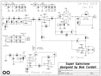 Figure_1.png111.4 KB · Views: 9,758
 -
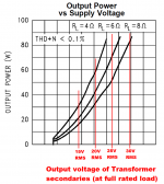 Figure_8.png41.5 KB · Views: 2,303
 -
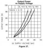 Figure_7.png40.7 KB · Views: 2,679
 -
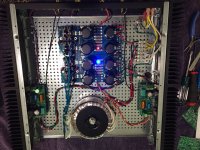 Figure_6.jpg493.6 KB · Views: 3,499
 -
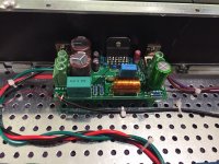 Figure_5.jpg503.6 KB · Views: 7,637
 -
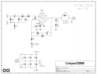 Figure_4.png58.2 KB · Views: 8,433
 -
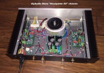 Figure_3.jpg544.2 KB · Views: 7,900
 -
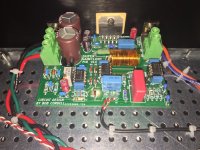 Figure_2.JPG432.2 KB · Views: 8,877
 -
Rev2_Parts_Lists_and_Mouser_Shopping_Carts_3_pcbs.zip22.4 KB · Views: 790
Last edited:

That looks strikingly similar to Neurochrome modulus-86. Any chance you can create this project in easyeda to make it open source?
The Neurochrome Modulus-86 is a composite amplifier, the Super Gainclone is not. A composite amplifier, such as the Modulus-86, uses a precision opamp to provide error correction on a less precise power amplifier.
Tom
Hey Mark,
Nice to see someone else giving the Cordell SGC a go! I love the sound of mine.
I'm sure your layout is way better than mine. Any chance of some bare board photos? I'd like to see where I could improve on my layout.
How did you find the Klipper? I'd thought of using the SGC as a guitar amp. Bob mentioned to me in an email that the Klipper gave the amp a tube sound when turned on and adjusted. I ended up leaving the KK out in my final build as my primary use was for listening to music but the bigger plus for me, was that it made my layout way simpler; something I'm not the best at!
I noticed that in Bob's original schematics there are two 1k resistors... Fig 27.3, R6, 1k resistor and then on Fig 17.4, R1, 1k. These equate to your R9. I thought it a little strange to have two 1k resistors and did basically the same as you and only used one! My thinking was that having the extra 1k would attenuate the signal into the KK and that really R6 and R1 on Bob's shematics are really one and the same! Is this correct, or did I miss something?
I find it interesting/odd that the layout of Mark's PCB is eerily similar to the layout of the Neurochrome Modulus-86 amp. Obviously the circuit is different -- a copy of Cordell's design rather than Tom's composite topology -- but the component placement and general layout configuration are highly reminiscent of the Modulus
Layout wise, I'm a bit puzzled by the compact one. Is it wise to run the input tracks along the output inductor ?
Any measurements on these boards ?
For a pair of stereo lm3886 at these voltages, a 160VA transformer is also widely sufficient, unless you're running sinewaves continuously.
Any measurements on these boards ?
For a pair of stereo lm3886 at these voltages, a 160VA transformer is also widely sufficient, unless you're running sinewaves continuously.
Bob's book covers the Klever Klipper pretty thoroughly. Figure 21.5 shows distortion vs output power (a) with Klever Klipper disabled; (b) with Klever Klipper enabled. The curves begin to diverge at about ~ 22 Watts.
One reason why I included connector J4 on the PCB, which enables or disables the Klever Klipper by installing / removing a header block, was to let builders experiment with the Super Gain Clone both ways. Listen and/or measure with it enabled, then again with it disabled. If you now have a strong preference, use the amp in that configuration.
Another reason was, I noticed that almost all of the other S.G.C. implementations which Google finds, omit the Klever Klipper entirely. It seems that not everybody wants the KK, perhaps because you need a couple of high wattage 8 ohm load resistors and an oscilloscope to set the KK soft-clip threshold. I decided to make it easy to completely omit the Klever Klipper if you don't want it, or if the adjustment procedure intimidates you, or if you'd rather not pay for the components which implement it. For example: the gold plated, milled-pin DIP8 socket for the KK dual opamp, costs $0.28 qty=1. And that's just the tip of the iceberg.
_
Last edited:
In a way, that is to be expected. If you decide to develop a new car, chances are that it looks eerily like another car ;-)
Have you seen the new Tesla truck? Doesn't look like my 1953 GMC or today's F-150.

This Klever Klipper ... I'm just wondering how much distortion its produce way before the clipping. Because I see that diodes are involved....
Perhaps best discussed in its own thread? Mark is simply implementing an existing plan, maybe leave this thread clear for his build?
The diodes "stand up" on a DC voltage. Diode conduction will be super-small for small to medium signals.
The LM power amps are complex things and do complicated things when clipped. They are exceptional quality for money, but were aimed at "better Consumer" gear, not "high end".
The diode clipper, when pushed past the DC bias, will clip in a "simple" way. Very predictable exponential, Shockley's Law. If you can't build an amp 10 times more powerful than you need, a biased diode is probably the best alternative way to limit the ill-effects of clipping.
Tom's (Neurochrome) board design drew a lot from what he learned from the DiyAudio collective in this thread, if anyone cares.
It is point to point but I'm sure lessons learned went into the PCB layout:
LM3886 PCB vs Point-to-Point (with data)
Is there a reference PCB design? I'll look for it.
In any case the chip pin out combined with common sense and short lead length drives the layout.
It is point to point but I'm sure lessons learned went into the PCB layout:
LM3886 PCB vs Point-to-Point (with data)
Is there a reference PCB design? I'll look for it.
In any case the chip pin out combined with common sense and short lead length drives the layout.
Last edited:
Tom's (Neurochrome) board design drew a lot from what he learned from the DiyAudio collective in this thread, if anyone cares.
It is point to point but I'm sure lessons learned went into the PCB layout:
LM3886 PCB vs Point-to-Point (with data)
Is there a reference PCB design? I'll look for it.
In any case the chip pin out combined with common sense and short lead length drives the layout.
People might want to build this amp with Tom's well thought out decoupling choices:
Taming the LM3886: Power Supply Decoupling – Neurochrome
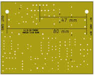
For convenience, the output inductor's winding instructions are printed on the back silkscreen layer. This inductor consists of 20 turns of AWG20 wire, tightly wound on a 7/16 inch diameter cylinder. It comes out to slightly less than 20mm long, which is handy because you want to wrap the coil with one or two layers of heat-resistant Kapton tape, 20mm wide. link 1. Wrap the coil with Kapton tape before you remove it from the underlying cylinder (the "coil former" rod), ensuring it stays tightly wound. If it's easier for you to buy a cylinder in metric units rather than inches, 11mm diameter would be just fine too.
My coil former was a metal rod I bought at the hardware store link 2 but you could also find one at a big box home improvement store link 3. I personally have not tried 7/16" wooden dowels, but they do exist and they are cheap. For example link 4. I imagine you want very hard wood that does not "give" when the coil windings are tightly applied, so the finished coil actually will slide off the rod after it's wound and wrapped.
There are lots of online websites that help you calculate the inductance of air core coils, the one that I prefer is
Inductance Calculation
Punch in the numbers for 20 turns of AWG20, tightly wrapped (no gap between adjacent wires) on a 7/16" core. I think you'll find it's about 2.3 microhenries.
The 10 ohm, 3 watt parallel resistor is positioned inside the wound coil, and the coil's lead wires are soldered to the resistor's legs. This saves a bit of room on the PCB.
_
Attachments
Last edited:
- Home
- Amplifiers
- Chip Amps
- Bob Cordell's Super Gain Clone PCB (LM3886) and a stripped-down version: Compact3886