Thanks for the comprehensive reply Mark. It looks like I was seeing a problem that isn't there!
I've added myself to the Group buy for two each of SGC and Compact3886 so I guess I have the bases covered. I plan to use the Compact for the OB bass unit and I guess if I'm feeling insecure I can always add a DC protection circuit.
Cheers
Ray
I've added myself to the Group buy for two each of SGC and Compact3886 so I guess I have the bases covered. I plan to use the Compact for the OB bass unit and I guess if I'm feeling insecure I can always add a DC protection circuit.
Cheers
Ray
Offset is a non issue in the "compact" because of C7 that reduce the gain at DC and C1 which isolates the input.
Both are missing in Peter Daniel's kit which got rid of all the components Peter deemed unnecessary. Thankfully, Mark didn't and as such I don't understand why he's linking his design to such misguided former designs.
Both are missing in Peter Daniel's kit which got rid of all the components Peter deemed unnecessary. Thankfully, Mark didn't and as such I don't understand why he's linking his design to such misguided former designs.
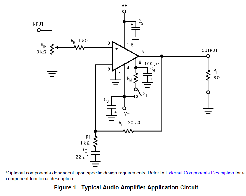
The "unity gain at DC" capacitor is present in TI's Typical Application Circuit, they call it "*Ci". On the Compact3886 schematic in post 1, its name is "C7". I happen to like the Nichicon Green Sleeve nonpolar capacitors, so I spec'd one in that position.
The input coupling capacitor was copied from the Super Gain Clone into the Compact3886. I spec'd a polypropylene capacitor in that position: it's C1 on Compact3886 schematic.
The input coupling capacitor was copied from the Super Gain Clone into the Compact3886. I spec'd a polypropylene capacitor in that position: it's C1 on Compact3886 schematic.
Since we're getting technical, it's possible to remove the influence of that cap by the respective sizing of the input and feedback caps. The input cap (a high quality mkp) should set the high pass filter f3 frequency. The feedback cap value is then selected to set a f3 point which is significantly lower. No voltage will thus develop across the feedback cap and its influence vanishes.The "unity gain at DC" capacitor is present in TI's Typical Application Circuit, they call it "*Ci". On the Compact3886 schematic in post 1, its name is "C7". I happen to like the Nichicon Green Sleeve nonpolar capacitors, so I spec'd one in that position.
This has been discussed at some length here: Negative Feedback Caps - Bipolar OK?
Sure, feel free to do that if you like. The PCB footprint sizes of those capacitors are included in the detailed Parts List. Or, if you can participate in a really high volume Group Buy like the one going right now, an extra couple of PCBs become very inexpensive: only $1.50 each. Experiment with different capacitor possibilities, on the PCB itself.
I've finally finished my Bob Cordell Super Gain Clone on Mark's boards.
I was held up as DHL sent my Mouser order to me in NZ then in their wisdom then sent it to Argentina, who then sent it back to the States. Eventually I received it.
And the last 20% of the build seems to take 80% of the time
The amp sounds very good; highly recommended.Very good bass. Quiet and clean. Very good.
Thank you Mark and Bob.
Two little negatives; a pop at turn-on which I guess is the DC offset before the servo kicks in, and a nasty "crack" a couple of seconds after turn-off which might be the reverse situation. I could do without the turn-off crack on my 104dB compression drivers.
Again, thank you Mark and Bob.
to dhssettim: wow, that's surprising! The LM3886 has a mute feature built-in to the chip, which the Super Gain Clone board enables exactly as per the datasheet. None of the four SGC amps I've built and listened to, have had any turn-on or turn-off thumps at all.
Could you say a little more about the power supplies being used? Are they the "PSU for Chipamps" boards from this site? Other boards? SMPS's? What are the details?
Referring to the Super Gain Clone schematic attached to post #1 of this thread, capacitor "C23" is connected to the MUTE pin of the LM3886. Is there a chance it is installed "backwards"?
Hi Mark,
Thank you for your concern.
First let me say that the bass of this wee amp is awesome.
I used the "PSU for Chipamps" boards and your Mouser component list.
Built exactly as specified though I added two cardboard tubes on the 1st 2 PS caps to protect them from the heat of the rectifier heatsinks a little.
I have used a +/-25Vac transformer as 22V wasn't available locally.
C23 (small red electrolytic) are both mounted with the negative stripe close to the heatsink side. I'll recheck the soldering as I've been known to make cold solder joints.
I've installed the Klever Klipper components though I haven't enabled it yet.
I've wasted much of this morning listening.
tim
You need some 1mm diameter enamelled copper wire (a.k.a. magnet wire), something cylindrical about 15 to 20mm to wind it around, use one of many website inductor calculators to figure out the turns count, wind it, finish the ends to shape and use sandpaper to strip off the enamel.
Someone's bound to have a YT video about winding air-cored inductors.
Someone's bound to have a YT video about winding air-cored inductors.
thank you both. all this is exactly what i needed. before anything elkse i needed to know the value in henries and where to solder it.
i seem to have some 14awg and since based on post #20 target value is 2.3 microhenries, maybe i can use one of those calculators to find the number of turns required for the same diameter but with 14awg wire. unless i'm missing something it shoyuld work the same, right?
i seem to have some 14awg and since based on post #20 target value is 2.3 microhenries, maybe i can use one of those calculators to find the number of turns required for the same diameter but with 14awg wire. unless i'm missing something it shoyuld work the same, right?
Last edited:
Yes, you could install a volume control potentiometer in front of a super gain clone. I wouldn't use anything higher than about 25K or so. However, I haven't tried this myself. The amps I've built so far, have all been fixed gain "power amplifiers" that are driven by a preamp. The volume control is part of the preamp in this arrangement.
Thanks Mark. I don't use a pre-amp as I have more than enough gain from my DAC, which also has a digital volume control, however, I plan to use one pair of these chip amp boards to drive the bass speaker in an open baffle and I'm pretty sure I will need to trim the gain to match the low-powered valve amp I will be using with the main full-range speaker.
Ray
Ray
- Home
- Amplifiers
- Chip Amps
- Bob Cordell's Super Gain Clone PCB (LM3886) and a stripped-down version: Compact3886