With all the work that I'm doing on the SWTPC Tiger amps I'm thinking that I should put a
pair of these in one of the many chassis that I have:
Tiger Amp Madness!
The Tiger .01 s have +/- 40V supplies that just squeak under the +/- 42 V max.
I'd use the metal tab version and run the heatsink hot with no insulator.
This would of course be too easy and take the fun out of figuring out the old Tiger designs.
Last edited:
The Keratherm thermal pads sold in the diyAudio Store, have Very Good thermal conductance (datasheet). You can see one of them in action: 2nd image attached to post #1 of this thread.
I got a request by email to state the PCB dimensions. They are:
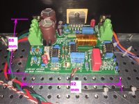
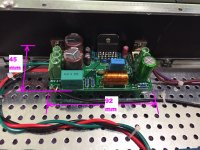
Super Gain Clone: 92 mm X 68 mm
Compact3886: 92 mm X 45 mm
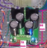
PSU for Chipamps: 98 mm X 78 mm
_
Super Gain Clone: 92 mm X 68 mm
Compact3886: 92 mm X 45 mm
PSU for Chipamps: 98 mm X 78 mm
_
Attachments
Last edited:
... I noticed 2 PSU boards for stereo Compact 3886. Special reason for this?
Whoops, look at post #1 again. It says,
... and Figure 6 is a complete stereo amplifier using two Compact3886 amp boards. ... Figure 6 shows a complete amplifier using the Universal Power Supply PCB [from the diyAudio Store].
That's the answer you seek.
I built one amp in a diyAudio Store / Modu Shop Dissipante 2U-tall X 300mm-deep chassis, using 2xSGC and 1xPSU_for_Chipamps. Its photograph was Figure 5.
I build a second amp in a diyAudio Store / Modu Shop Dissipante 2U-tall x 400mm-deep chassis, using 2xCompact3886 and 1xUniversal_Power_Supply_PCB. Its photograph was Figure 6.
One PSU_for_Chipamps will support two LM3886s, whether they be SGC or Compact3886. Whether they be stereo or monobloc-bridged. (You supply the necessary extras to make bridging possible).
alternative resistors
Mark,
I am accumulating and buying parts .
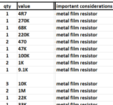
Can I substitute all resistors to 0.25 W ? this is with the exception of the R20 10R 3 W zobel . I know that BOM states 0.6W.
Any preference between carbon or metal film ?
any great penalty between 1% and 5% tolerance.
Thank you
Mark,
I am accumulating and buying parts .
Can I substitute all resistors to 0.25 W ? this is with the exception of the R20 10R 3 W zobel . I know that BOM states 0.6W.
Any preference between carbon or metal film ?
any great penalty between 1% and 5% tolerance.
Thank you
To actually give some useful guidelines...
No reason to use carbon anymore. The cost savings are minimal and metal films resistors are just better all around.
1% vs 5%. In many positions, it doesn't matter much. The exceptions are any resistors that influence the gain of your amp as it could impact the match between channels. R9-10, R11-13-14 and R15-r16 should be 1%.
Power dissipation: beside R19-20 which should be 2-3W, it is better to oversize the feedback resistor as it minimizes distortion due to thermal effect. That means R18 should be 0.6W. The rest can be 0.25W.
Good morning 00940
i do not catch the point with the 0,6W resistor: my calc...
if we have Ptot of the resistor about 0,25W then the max current is.
P 0,25 = I^2 *R --> I = Sqrt( P0,25/22000) = 3,3mA. if 3,3mA go through the resistor we should have a voltage of U=i+R = 3,3mA*22k = 74,16 Volts .
this resistor
RNMF14FTC22K0 Stackpole Electronics Inc | Resistors | DigiKey
if i read correctly you use a 22VAC 200VA transformer you will get max 31 VDC max = 62Volts rail to rail - so its the max of the complete psu and about 83,6% of the power what the resistor can handle.
so if i looked a a graph i found - pic - do you mean that the rise of the temp =noise will be better we choose the next power rating? so yes you are right.")
but this is at max power of the amp
chris
i do not catch the point with the 0,6W resistor: my calc...
if we have Ptot of the resistor about 0,25W then the max current is.
P 0,25 = I^2 *R --> I = Sqrt( P0,25/22000) = 3,3mA. if 3,3mA go through the resistor we should have a voltage of U=i+R = 3,3mA*22k = 74,16 Volts .
this resistor
RNMF14FTC22K0 Stackpole Electronics Inc | Resistors | DigiKey
if i read correctly you use a 22VAC 200VA transformer you will get max 31 VDC max = 62Volts rail to rail - so its the max of the complete psu and about 83,6% of the power what the resistor can handle.
so if i looked a a graph i found - pic - do you mean that the rise of the temp =noise will be better we choose the next power rating? so yes you are right.
but this is at max power of the amp
chris
Attachments
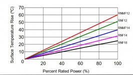
You can do it more easily... The feedback resistor sees the full output voltage. Let's say about 28V in your example. That gives us about 1.3ma and an instant dissipation of 36mW.
What we're concerned about is the variation in the value of the resistor vs heat. These variations might be small but aren't corrected by the global feedback. As music is made of always changing transients, it wouldn't be easy to exactly quantify the phenomenon. It's just easier (and cheap) to strongly oversize the feedback resistor. AndrewT suggested a 10% ratio between the actual max dissipation and the rating of the resistor. A 1/2W resistor is thus indicated in this case.
What we're concerned about is the variation in the value of the resistor vs heat. These variations might be small but aren't corrected by the global feedback. As music is made of always changing transients, it wouldn't be easy to exactly quantify the phenomenon. It's just easier (and cheap) to strongly oversize the feedback resistor. AndrewT suggested a 10% ratio between the actual max dissipation and the rating of the resistor. A 1/2W resistor is thus indicated in this case.
You can do it more easily... The feedback resistor sees the full output voltage. Let's say about 28V in your example. That gives us about 1.3ma and an instant dissipation of 36mW.
What we're concerned about is the variation in the value of the resistor vs heat. These variations might be small but aren't corrected by the global feedback. As music is made of always changing transients, it wouldn't be easy to exactly quantify the phenomenon. It's just easier (and cheap) to strongly oversize the feedback resistor. AndrewT suggested a 10% ratio between the actual max dissipation and the rating of the resistor. A 1/2W resistor is thus indicated in this case.
Thank you for that clear words 00940 !!
Actually the Amp Camp Amp chassis heat sinks have their own UMS which is 3 holes in a row! I’ll find it and post it here. Maybe too late for this board batch of PCBs but it would make it easier to build if the holes in the PCB corresponded with this existing UMS. The ACA chassis might not be wide enough for the PSU, but we could probably supply the sinks with a wider version of the chassis
Unlike the PCBoards which follow the diyAudio Universal Mounting Specification ("UMS"), the Super Gain Clone PCB and the Compact3886 PCB are mounted perpendicular to the heatsink. So they are certainly not compatible with UMS. You will have to drill and tap three holes for each amp PCB; one hole to bolt the LM3886 to the heatsink, and two more holes to bolt the PCB support L-Brackets to the heatsink. A drilling template will be provided in the pdf documentation that I expect to complete soon. When? Soon. How soon? Soon.
In fact, drilling and tapping your own holes is inevitable, because the very slick-looking 2U chassis in the Store are only available with undrilled and untapped heatsinks. (2U is not tall enough to accomodate the UMS footprint). Luckily, 3 holes is not a large number to drill and tap, even for a beginner. And remember, if you make a mistake, you can slide the template 10mm left or right and try again. The PCBs are short while the heatsinks are long. The "extra" holes will be inside the chassis and invisible to onlookers.
_
Last edited:
It's a long time since I built a solid-state amplifier (well, apart from the Noir HPA I've just finished) and I'm not at all familiar with devices like the LM3886. I've added myself to the GB list as I can see a good use for a couple of these amps - I'm thinking of a SGC for a spare room system and a Compact3886 for bass duty on an open baffle project.
Just wondering about DC offset at the speaker terminals; the SGC has a DC Servo arrangement, which I assume is what facilitates the absence of a coupling cap, but it's been removed from the Compact3886 - does that imply the need for an output cap or a DC protection circuit on the C3886?
Apologies for the rather basic question.
The LM3886 datasheet recommends "Typical Application Circuits" which direct couple the LM3886 output to the loudspeaker, without a DC servo. And this is the way many many of the early Gainclones were built; for example take a look at Peter Daniel's circa 2008 manual, here. Compact3886 is just another genetically identical descendant from those ancestor designs. They all have the same offset voltage non-problem (or: problem, if you feel that way).
However if you are very concerned about offset voltage, the Super Gain Clone board includes a DC servo (as you noted), which drives the output offset down below ~ 5 millivolts. Its PCB is only 23mm longer than the Compact3886 as shown in post #23 above. And the cost to purchase its electronic components is not hugely greater than the cost for the Compact3886's parts. Load up the "one click Mouser.com shared shopping cart" for each and note the total price at bottom right.
_
However if you are very concerned about offset voltage, the Super Gain Clone board includes a DC servo (as you noted), which drives the output offset down below ~ 5 millivolts. Its PCB is only 23mm longer than the Compact3886 as shown in post #23 above. And the cost to purchase its electronic components is not hugely greater than the cost for the Compact3886's parts. Load up the "one click Mouser.com shared shopping cart" for each and note the total price at bottom right.
Math note: DC power dissipated in the voice coil of a 4 ohm woofer, due to an amplifier output offset voltage of V volts, is:
- P = (V * V / 4) watts
_
Attachments
- Home
- Amplifiers
- Chip Amps
- Bob Cordell's Super Gain Clone PCB (LM3886) and a stripped-down version: Compact3886