I exchanged the two 22uF caps with 470uF + 100nF X7R each, but to no avail. Still getting the same oscillations with the standard circuit and when adding 220pF or more to the output.
Playing around with the Zobel didn't help either. Adding 47nF in series to reduce the capacitance didn't show any real effect. Adding 2R2 in series to increase the resistance led to severe oscillations when the output cap was added. Adding both parts to increase the resistance and decrease the capacitance at the same time led to the same severe oscillations.
EDIT: Funny thing. The fully compensated 6dB circuit now is actually looking more stable than the standard circuit: Adding 220pF to the output doesn't result in oscillations anymore, and the 1nF oscillations look a little less severe.
Last edited:
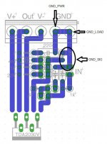
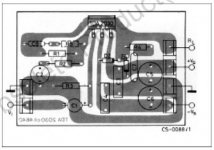
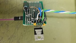
Me no likey.Here's a photo of the test circuit, along with the EAGLE layout and corresponding schematic, in case you want to trace each route exactly.
V+ / V- inductance should be decently low, but why would you route the output in between? Yeah, it does keep it away from the input, but...
V+ and V- to GND inductance is not that great.
Bypass caps in "Long-Legged Linda" mode with what seems like bends directly at the parts - (a) the latter may damage the caps and (b) the former does not exactly signify low inductance (why were these not underneath?). And where do they even go anyway? Not to ground by the looks of it.
No distinction between input ground and output ground. (Ground is ground, na na na-na-na...) This can really bite you in the rear end when it comes to ground loops. Try adding a preamp circuit fed from the same supply, and you'll probably see what I mean. (Countless DIY boomboxes suffer from problems because of this.) That said, since Tom Christiansen quite convincingly argues that this is the way to go, adapting everything else may be preferable. Still, you might consider inserting maybe 10 ohms into the ground between the 1n5 input cap and the 4n7 (maybe even ahead of the 1n5), with dedicated IGND and OGND connections.
Last edited:
Me no likey.
Me too, but I think I could have done worse. It's just a testbed after all, not a production model. Once I get rid of all those jumpers, the layout can get much more compact and optimized.
Bypass caps in "Long-Legged Linda" mode with what seems like bends directly at the parts - (a) the latter may damage the caps and (b) the former does not exactly signify low inductance (why were these not underneath?).
I have never seen a commercial chip amp that put the caps underneath the board. Granted, in this case it would have been easy (and I'm gonna try it), but it must be possible to do it the 'normal' way. Compared to the generously spaced parts on the sample layout in the datasheet I'm already pretty compact here.
That said, since Tom Christiansen quite convincingly argues that this is the way to go, adapting everything else may be preferable.
Yeah, Tom and his grounding mantra. In another thread I once argued with him about his impeccable simulation results, because when I replicated them and added some length of speaker wire into the mix, the results didn't look that great anymore. However, I think I'm not too far off from what he suggests actually. Nonetheless, I'll try to make it better. I can only learn along the way, nothing to lose here
 .
.Attachments
Here's a second attempt at the supply decoupling. Same result. Tested it with another power supply and a different load resistor, connected with shorter leads directly to the screw terminals, but it's still breaking into oscillations with an additional 220pF.
Attachments
I smell a rat somewhere: the impedance of a 220pF cap is disproportionately high compared to the 1 ohm Zobel: the time constant is 220ps.
For such a chip, the Ft of the process must be 40Mhz or thereabout, and whatever happens in the GHz range should not matter, unless the Zobel is not really present or has an incorrect value: a dry solder, a 1 ohm which is in fact a 100 ohm, a capacitor internally open...
For such a chip, the Ft of the process must be 40Mhz or thereabout, and whatever happens in the GHz range should not matter, unless the Zobel is not really present or has an incorrect value: a dry solder, a 1 ohm which is in fact a 100 ohm, a capacitor internally open...
Hi
i am for sure no expert but you use a TDA2030 - this could be fake chip and therefore they can do a lot of strange things.
i tried to put a 10k, 20k and 30k square wave signal to the input to "see" better the oscillation at the output. - this brought me to add a 100pF cap in parallel to the feedback resistor.
chris
Just a suggestion: try to add a couple-100pf cap between the + and - opamp inputs. This can stop some chipamps from oscillating. No guarantees though.
Tested with 110pF, 220pF, 440pF and 47nF (yes, nano) to no avail. THD increased a lot with 47nF, but the oscillations are not remedied.
I smell a rat somewhere: the impedance of a 220pF cap is disproportionately high compared to the 1 ohm Zobel: the time constant is 220ps.
For such a chip, the Ft of the process must be 40Mhz or thereabout, and whatever happens in the GHz range should not matter, unless the Zobel is not really present or has an incorrect value: a dry solder, a 1 ohm which is in fact a 100 ohm, a capacitor internally open...
Okay, I'll toss them out and try some other parts. Let me see what I can find.
i am for sure no expert but you use a TDA2030 - this could be fake chip and therefore they can do a lot of strange things.
Good point. Today they're faking everything, even something like what is probably the cheapest chip amp around today...
(...) unless the Zobel is not really present or has an incorrect value: a dry solder, a 1 ohm which is in fact a 100 ohm, a capacitor internally open...
Elvee, you're a genius!! Looks like the resistor was the culprit! It measures 1.19 ohm on my UNI-T multimeter, so the value is about correct, but it's a 2W wirewound type. Maybe the inductive part was just too much in that case? I have replaced it with a 1R 1% metal film resistor (didn't know I had them, else I had used one of those in the first place), and now the picture looks a little different. I actually cut one of the resistors legs a few days ago already, to see how the circuits behave without the Zobel present. The result was a huge increase in oscillations when adding capacitance to the output, so I reconnected it and was convinced that the Zobel is doing its job.
The standard circuit is now immune to adding 220pF, 1nF or even 47nF to the output.
The circuit supposed by PRR is also fine.
The PRR circuit with the added capacitor across the feedback resistor is already oscillating without any capacitor added to the output now, just like you predicted a couple of posts back. Funny thing that it used to have the best THD values before, but is practically unusable now.
Oh yes it was: if there is a single spot where any inductance can cause trouble, that's the one.but it's a 2W wirewound type. Maybe the inductive part was just too much in that case?
The Zobel makes sure the amplifier always sees an "acceptable" (meaning low and resistive) impedance throughout its full frequency range, and preferably a decade beyond to be completely safe, but if it becomes inductive at some point, things go seriously wrong

This looks like the high-freq ground return path went thru the 4n7 caps and the 47R resistor, in effect substituting for the zobel that went "open" in high-freqs beacuse of the zobel resistor self-inductance....
EDIT: Funny thing. The fully compensated 6dB circuit now is actually looking more stable than the standard circuit: Adding 220pF to the output doesn't result in oscillations anymore, and the 1nF oscillations look a little less severe.
...
Okay, here's another (probably final) test.
To compare apples to apples, I have made all the following graphs this evening in one run and didn't re-use any of the previous graphs from the last days.
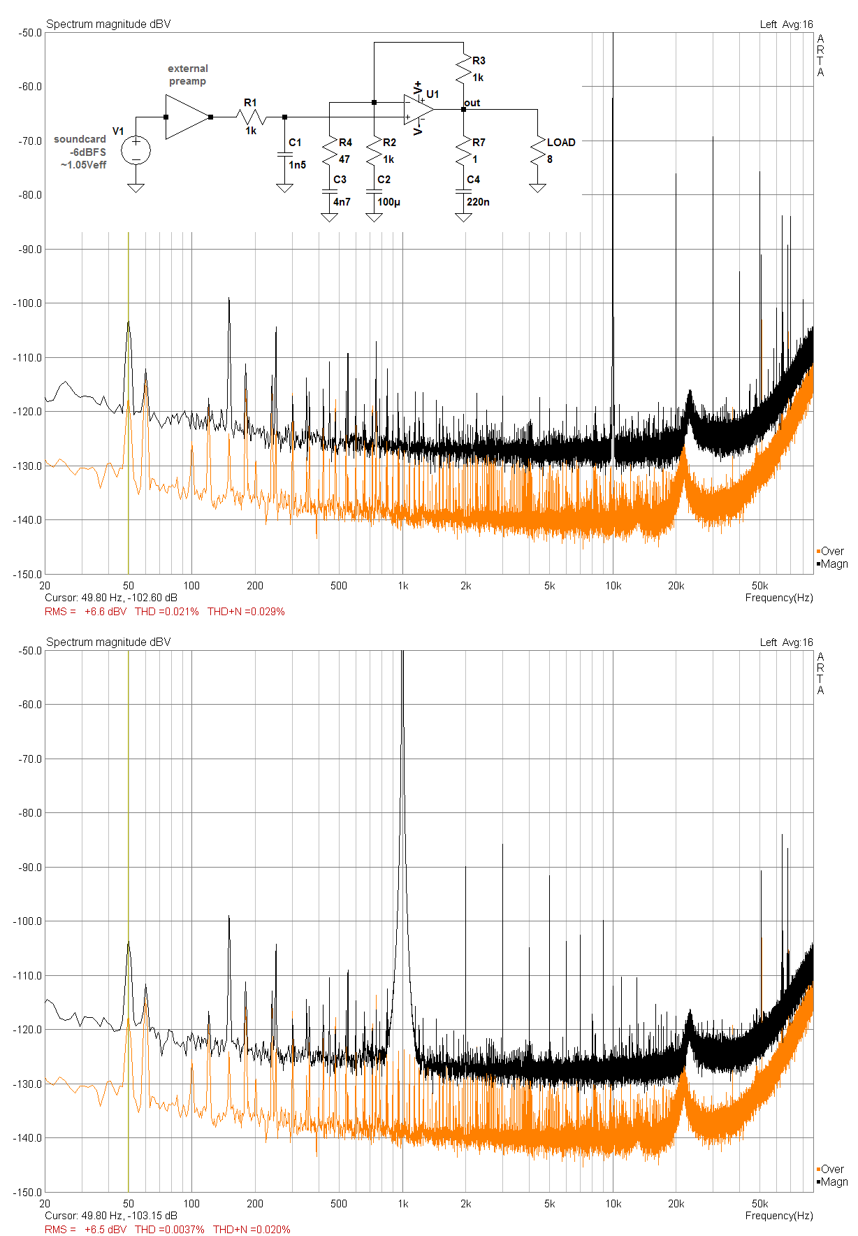
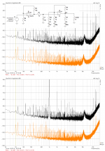
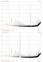
First off, here's the noise-gain compensated TDA2030A as proposed by PRR again, set to 6dB gain only. It is fed directly from the soundcard with -6dBFS output level (ca. 1.05V RMS), which is about the sweet spot for lowest distortion and noise.
Into 8 resistive Ohms I measured a THD of 0.0039% at 1kHz and 0.041% at 10kHz. The noise floor dips down to around -130dBV in the 10kHz range, which is considerably lower than what the standard circuit with a suggested minimum gain can achieve.
(The orange trace shows the measurement noise floor with everything hooked up and happily picking up stray noise, but with the DUT still powered off.)
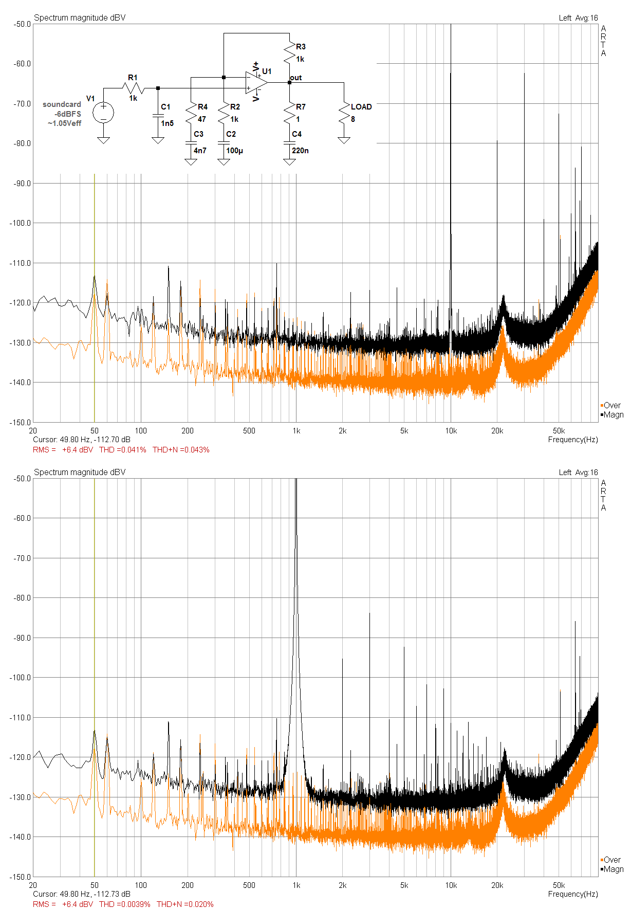
Next up is what I had in mind when I started this whole experiment. Now I've added my own preamp (with input selector and PGA attenuator) into the mix. I have left the soundcard output at the same level of -6dBFS and used the preamp's volume control to arrive at the same +6.5dBV output into the load.
As expected, the noise floor increased a bit, but only by a little 2 or 3 dBV, which is actually less than I had imagined. The THD at 1kHz is about the same with 0.0037%, but the value at 10kHz got almost cut in half to 0.021% now, which is a nice improvement!
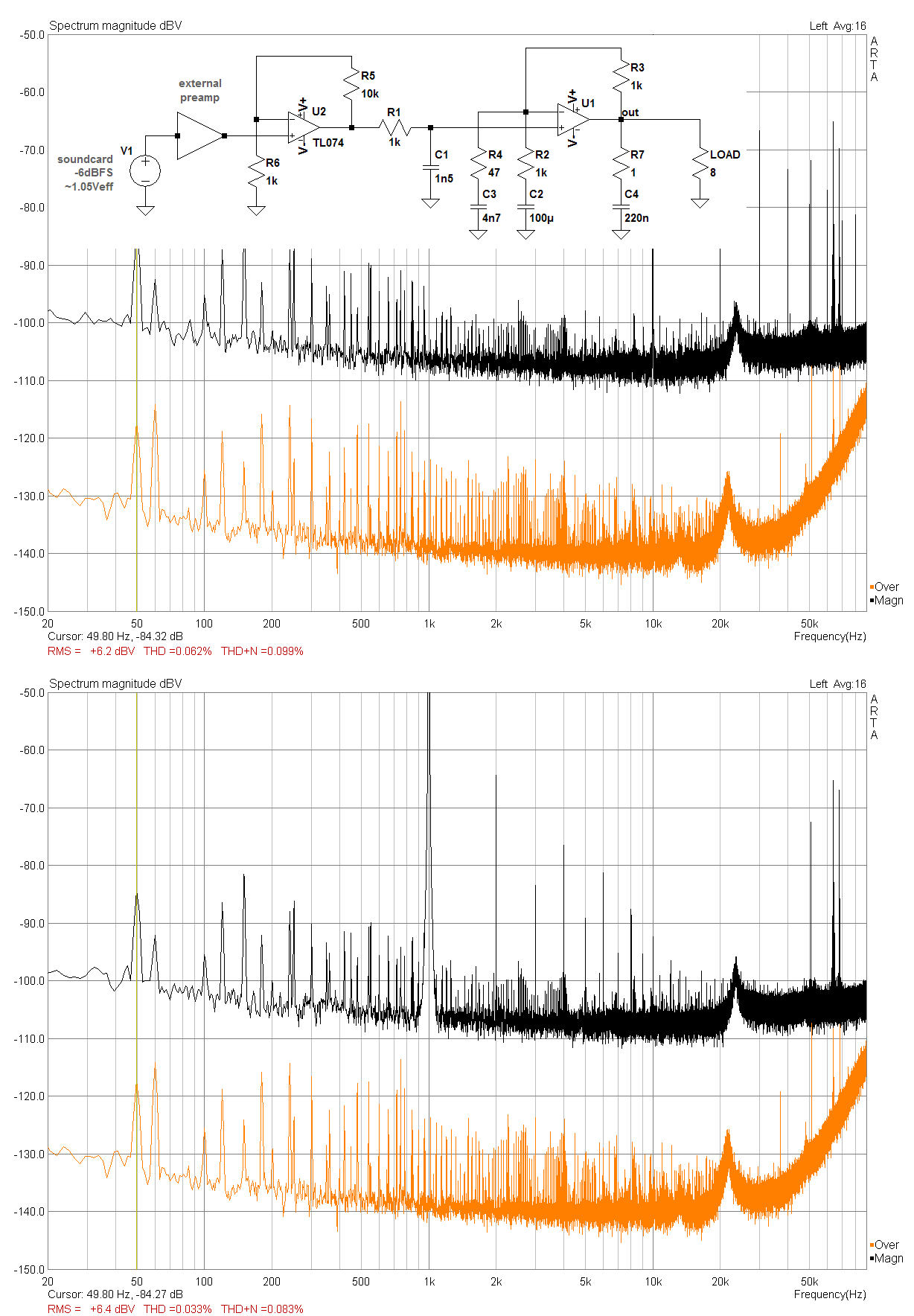
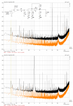
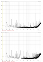
As another means to compensate for the low gain of 6dB, I removed my preamp and added a simple non-inverting 20dB gain stage at the input instead, made up of a cheap TL074 jellybean opamp. The performance of this circuit is (within a small margin) about the same as the standard circuit set to a similar gain of 27dB. Because of that I didn't measure that one again, as the graphs would be almost the same as these.
Now the noise floor doesn't even reach -110dBV, which is about as bad as it gets. THD at 1kHz is an order of magnitude worse, which is on par with what I have measured before with the standard circuit. THD at 10kHz is also worse with 0.054%, but not by as much as at 1kHz.
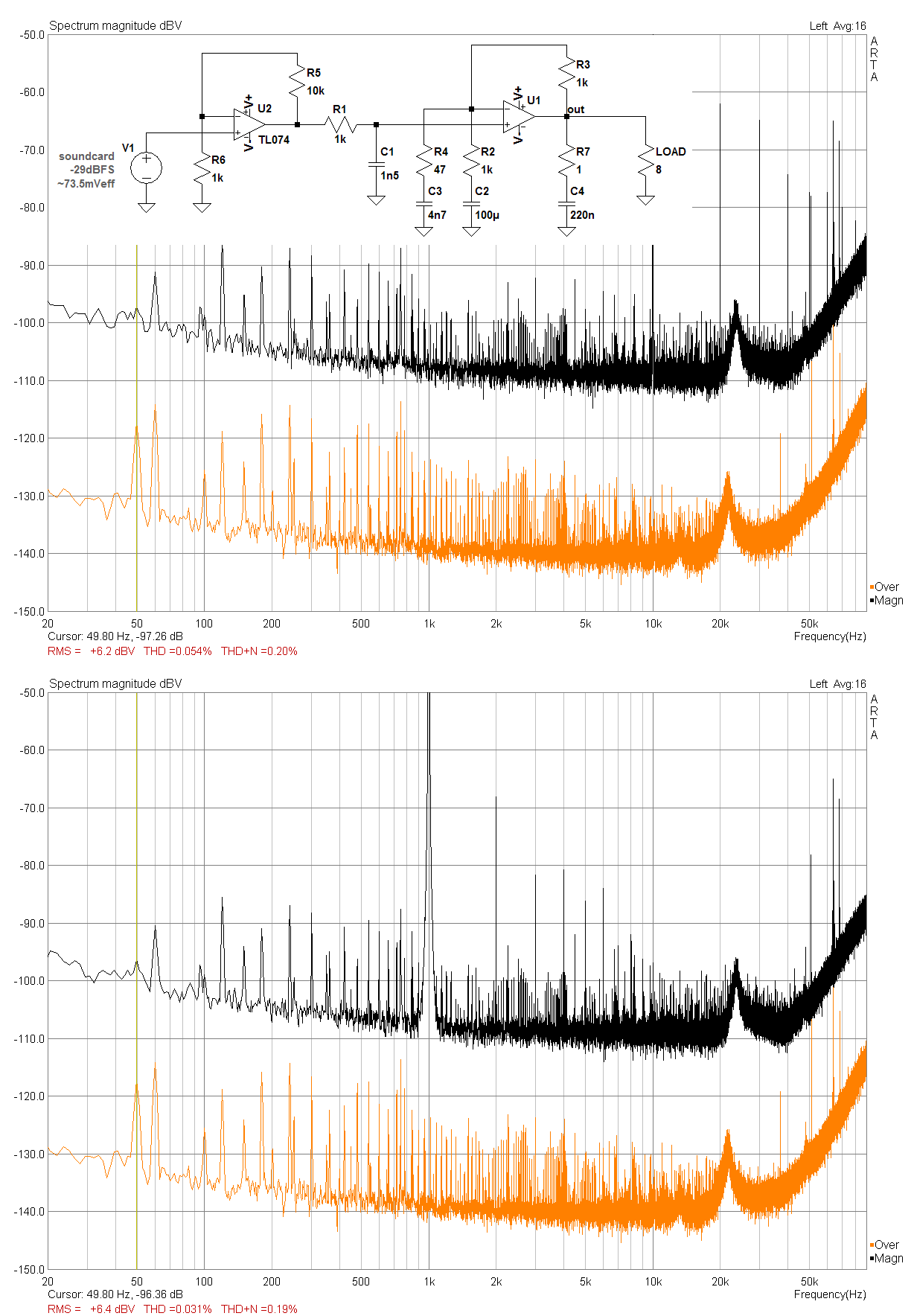
To arrive at this values, I had to lower the soundcard output to -29dBFS (73.5mV RMS) for the same output power. As this probably has some negative effect on the THD performance of the soundcard output, I went a little apeshit and added my preamp back into the mix .
.
Now we have the same -6dBFS soundcard output, attenuated down by an external preamp, upped by 20dB with a crappy TL074 and finally another 6dB by the TDA itself. Which is about the same as setting the TDA gain to 26dB in the first place and leaving out the '074, just a little more crazy. Let's see:
The noise floor again rose by 2 or 3 dBV, which is what the external preamp adds. THD didn't get any better though, it's even a little worse again.
What's your opinion?
I think the results look pretty good! Since my preamp will always be in front of every amp I'll be using anyhow, and can put out enough juice to drive a little TDA with +-22V supplies and only 6dB gain into saturation easily, I'll probably build two of these little buggers just for the fun of it and give them a listen.
In case I should actually manage to fry my tweeters along the way, I won't hesitate to report back here!
To compare apples to apples, I have made all the following graphs this evening in one run and didn't re-use any of the previous graphs from the last days.
First off, here's the noise-gain compensated TDA2030A as proposed by PRR again, set to 6dB gain only. It is fed directly from the soundcard with -6dBFS output level (ca. 1.05V RMS), which is about the sweet spot for lowest distortion and noise.
Into 8 resistive Ohms I measured a THD of 0.0039% at 1kHz and 0.041% at 10kHz. The noise floor dips down to around -130dBV in the 10kHz range, which is considerably lower than what the standard circuit with a suggested minimum gain can achieve.
(The orange trace shows the measurement noise floor with everything hooked up and happily picking up stray noise, but with the DUT still powered off.)
Next up is what I had in mind when I started this whole experiment. Now I've added my own preamp (with input selector and PGA attenuator) into the mix. I have left the soundcard output at the same level of -6dBFS and used the preamp's volume control to arrive at the same +6.5dBV output into the load.
As expected, the noise floor increased a bit, but only by a little 2 or 3 dBV, which is actually less than I had imagined. The THD at 1kHz is about the same with 0.0037%, but the value at 10kHz got almost cut in half to 0.021% now, which is a nice improvement!
As another means to compensate for the low gain of 6dB, I removed my preamp and added a simple non-inverting 20dB gain stage at the input instead, made up of a cheap TL074 jellybean opamp. The performance of this circuit is (within a small margin) about the same as the standard circuit set to a similar gain of 27dB. Because of that I didn't measure that one again, as the graphs would be almost the same as these.
Now the noise floor doesn't even reach -110dBV, which is about as bad as it gets. THD at 1kHz is an order of magnitude worse, which is on par with what I have measured before with the standard circuit. THD at 10kHz is also worse with 0.054%, but not by as much as at 1kHz.
To arrive at this values, I had to lower the soundcard output to -29dBFS (73.5mV RMS) for the same output power. As this probably has some negative effect on the THD performance of the soundcard output, I went a little apeshit and added my preamp back into the mix
.Now we have the same -6dBFS soundcard output, attenuated down by an external preamp, upped by 20dB with a crappy TL074 and finally another 6dB by the TDA itself. Which is about the same as setting the TDA gain to 26dB in the first place and leaving out the '074, just a little more crazy. Let's see:
The noise floor again rose by 2 or 3 dBV, which is what the external preamp adds. THD didn't get any better though, it's even a little worse again.
What's your opinion?
I think the results look pretty good! Since my preamp will always be in front of every amp I'll be using anyhow, and can put out enough juice to drive a little TDA with +-22V supplies and only 6dB gain into saturation easily, I'll probably build two of these little buggers just for the fun of it and give them a listen.
In case I should actually manage to fry my tweeters along the way, I won't hesitate to report back here
!Attachments

..the impedance of a 220pF cap is disproportionately high compared to the 1 ohm Zobel....
I see 220nFd there? 0.2uFd is reasonable. It damps nominal 8 Ohm load at 200kHz, which is where device hFE starts to fall; is down to 1 Ohm at 1.6MHz where output devices are about dead.
TDA2030 are well known to die much sooner than that......
at 1.6MHz where output devices are about dead.
...
Say a wrong word, curse a bit - and out comes the magick smoke!
It looks logical: the 4n7/1K pole is at 33kHz, meaning the 3rd harmonic (which is probably dominant) will be fully attenuated by the increased loop gain.Okay, here's another (probably final) test.
To compare apples to apples, I have made all the following graphs this evening in one run and didn't re-use any of the previous graphs from the last days.
.....
What's your opinion?
The effect will die out at higher frequencies, but a benefit will still be felt for the 5th and 7Th
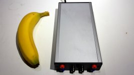
Here it is, a fully functional Stereo version of the 6dB TDA2030A. Banana for scale. Or for name? Why not call it "Chiquita"... sounds better than pesky little bugger
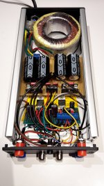
.Looks a little messy inside. Case is about 21 x 10 x 3.5 cm in size. Toroid is 2 x 12V 30VA for +-18.5V when idle. All of the parts were lying around and/or recycled.
This is the performance of one channel under the same conditions as with the last test (-6dBFS soundcard output, external preamp, 8R load). Measured mains noise got a little worse due to the PSU now being in close proximity to the amp itself, but that is really only measurable and totally inaudible! This thing is dead quiet, even with the ear against the speaker.
Total harmonic distortion once again got better over the last iteration, at 1kHz from 0.0037% to 0.0021% and at 10kHz from 0.021% to 0.0079%. Not bad.
This is maximum output into 8 Ohm, just before the onset of clipping. The scope showed an output swing of about 24Vpp at the load. The measurement output was taken at the 20% tap of the load resistor as to not overdrive the soundcard input into clipping.
I really like this little amp! Now on for some listening tests
Attachments
Did you do anything different (layout, component values, wiring) to get the lower THD rating?
I see you use a simple wire loop as soldering posts on the perfboard. If you twist the wire (on the component side), this becomes a much sturdier post. When soldered, it isn't that much inferior to commercial soldering posts - dosen't look as neat of course, but hey ....
P.s. IIRC Meier Corda Rock also used TDA2030. Perhaps they also use some clever engineering tricks?
- Status
- This old topic is closed. If you want to reopen this topic, contact a moderator using the "Report Post" button.
- Home
- Amplifiers
- Chip Amps
- Fun with a cheap TDA2030A at only 6dB gain