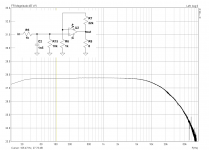
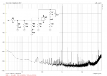
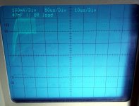
Still on the single-ended interface, I did some frequency response plots at 192k sampling rate. The peak at higher frequencies is clearly seen, and probably even higher than the 80kHz measurement limit of my soundcard.
However, it is easily remedied by adding another capacitor across the other feedback resistor. That actually brings down THD even more, from 0.0051% to 0.0020%!
However, it is easily remedied by adding another capacitor across the other feedback resistor. That actually brings down THD even more, from 0.0051% to 0.0020%!
Attachments
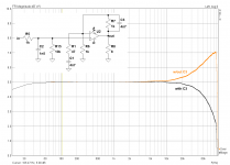
By doing that, you cancel the effect of the noise-gain network, making the amp operate at a gain of ~1, which will make it unstable or marginally stable.However, it is easily remedied by adding another capacitor across the other feedback resistor. That actually brings down THD even more, from 0.0051% to 0.0020%!
It may seem to work, but it is unadvisable: it is a good recipe for frying your tweeters
The whole "ultrasonic peaking" thing is expected - you are increasing ultrasonic gain to ~26 dB after all. If you had more bandwidth available you might find that it is actually more of a shelf than a peak, at least when doing away with the 1n5 temporarily. If you need to get rid of this, increase the order of input filtering.
Good ol' ESI Juli@. Still have one floating around, too. Neat hardware, drivers beyond my personal limit of acceptability.
Good ol' ESI Juli@. Still have one floating around, too. Neat hardware, drivers beyond my personal limit of acceptability.
Last edited:
imho this would be the way to do it...
(code for Analog Filter Applet )
======================
$ 0 5.0E-6 5 50 5.0 50
% 4 1378614.6781719956
g 176 240 176 288 0
w 272 192 272 240 0
a 272 176 416 176 1 15.0 -15.0 4000000.0
w 416 176 416 240 0
r 272 240 416 240 0 1000.0
r 176 240 272 240 0 1000.0
O 416 176 480 176 0
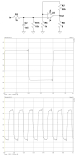
170 272 96 272 48 2 20.0 4000.0 5.0 0.1
c 176 240 176 192 0 2.2E-9 0.0
r 176 192 272 192 0 47.0
r 272 96 272 160 0 1000.0
c 272 160 128 160 0 1.0E-9 0.0
g 128 160 128 288 0
c 272 160 272 192 0 1.0E-10 0.0
r 272 96 128 96 0 10000.0
w 128 96 128 160 0
o 0 64 0 34 5.0 9.765625E-5 0 -1
======================
(code for Analog Filter Applet )
======================
$ 0 5.0E-6 5 50 5.0 50
% 4 1378614.6781719956
g 176 240 176 288 0
w 272 192 272 240 0
a 272 176 416 176 1 15.0 -15.0 4000000.0
w 416 176 416 240 0
r 272 240 416 240 0 1000.0
r 176 240 272 240 0 1000.0
O 416 176 480 176 0
170 272 96 272 48 2 20.0 4000.0 5.0 0.1
c 176 240 176 192 0 2.2E-9 0.0
r 176 192 272 192 0 47.0
r 272 96 272 160 0 1000.0
c 272 160 128 160 0 1.0E-9 0.0
g 128 160 128 288 0
c 272 160 272 192 0 1.0E-10 0.0
r 272 96 128 96 0 10000.0
w 128 96 128 160 0
o 0 64 0 34 5.0 9.765625E-5 0 -1
======================
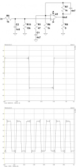
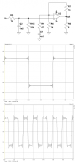
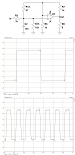
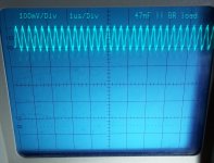
First, make a squarewave test on a resistive load: if you see any ringing or overshoot, you have a problem.
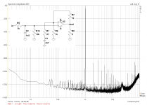
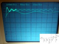
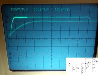
Doesn't look too bad, does it? Tested with 1kHz and 10kHz into 8R resistor, sampled with 192k.
If you need to get rid of this, increase the order of input filtering.
Do I actually need to get rid of it? I'm not sure it is a problem, since it is ultrasonic anyway. Of course it doesn't look that nice and it is certainly not "HiFi", but hey - we're talking TDA2030A here, it's never been HiFi in the first place...
(...) drivers beyond my personal limit of acceptability.
Why would that be? I'm currently using it in a dedicated machine running WinXP on an old Pentium 4 single core, because my contemporary hardware doesn't have a PCI slot anymore.
imho this would be the way to do it...
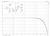
So you basically added another 100pF between the inv. and non-inv. input? Let's see if I can test that one.
Attachments
So you basically added another 100pF between the inv. and non-inv. input? Let's see if I can test that one.
Had to use 2x 220pF in series. Didn't make any measurable difference. Frequency response, THD, square wave all look the same.
It mostly depends on your OCD when it comes to square wave response.Do I actually need to get rid of it? I'm not sure it is a problem, since it is ultrasonic anyway. Of course it doesn't look that nice and it is certainly not "HiFi", but hey - we're talking TDA2030A here, it's never been HiFi in the first place...
") It just isn't nice when your out-of-band signals are amplified more than the in-band ones.
It just isn't nice when your out-of-band signals are amplified more than the in-band ones.And you are probably shutting that system down when you are done using it, as I would if I had a dedicated lab PC. My problem was that anything going in my main system (I did and still do have PCI slots) must support hibernation, and the Juli@ drivers just... don't. Quite officially. But yeah, something with XP that can use the old, non-"unified" drivers sounds perfect.Why would that be? I'm currently using it in a dedicated machine running WinXP on an old Pentium 4 single core, because my contemporary hardware doesn't have a PCI slot anymore.
You could still upgrade to something a little more recent and power-efficient should it be gathering dust somewhere, newer drivers for Envy24HT cards are multiprocessor-proof (BTDT). Intel Q43/45 chipset and Core 2 Quad still is quite doable (again, BTDT - FSC D2811 board, Q8200).
You cannot draw any serious conclusion: the first two pics show some ringing, but on the wrong side of the edge: before the transition actually occurs.Doesn't look too bad, does it? Tested with 1kHz and 10kHz into 8R resistor, sampled with 192k.
That's typical of a digital, FIR filter response. Normally, you should see the ringing on both sides of the transition, but bizarrely there is nothing afterwards, meaning there is probably some inadvertent compensation between real and Gibbs ringings.
The two other pics are more typical of what you can expect from a soundcard, but you cannot draw meaningful conclusions, because oscillations would occur somewhere around 1MHz, and only an oscilloscope (physical or virtual) has enough bandwidth to show this kind of problem reasonably accurately.
It mostly depends on your OCD when it comes to square wave response.
And you are probably shutting that system down when you are done using it, as I would if I had a dedicated lab PC.
That's right. I never got used to using hibernation under Windows, because it would always take only two or three cycles before something nasty would happen. Only doing proper shutdowns since then.
The two other pics are more typical of what you can expect from a soundcard, but you cannot draw meaningful conclusions, because oscillations would occur somewhere around 1MHz, and only an oscilloscope (physical or virtual) has enough bandwidth to show this kind of problem reasonably accurately.
Yeah, luckily me olde Hameg crapped out just yesterday
. I'll repeat that test once I got it back up running (and then use a properly band-limited square wave without ringing).It's alive again. Something wrong with the high voltage supply it seems, because a slap on the corresponding section brought it back to life.
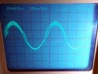
Here are two 'screenshots' of a 1kHz square wave into 8R; the ringing one generated by ARTA, the clean one made with Audacity.
Since my scope has a second time base, you can actually see the upper half wave at 50us/div, and the brighter part of the rising edge magnified to 10us/div at the same time. The scope has 100MHz of bandwidth. Still no signs of ringing I'd say.
Now to add some capacitance to the output, while the scope is still in working order?
Attachments
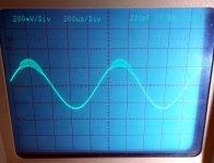
Adding 220pF to the output didn't make a difference, but a big leap up to 10nF made the amp oscillate. Even without an input signal the oscillations are visible on the scope.
I'll have to dig deeper in the parts bin for some values in between 220pF and 10nF. Any ideas on how to deduce the phase margin from this observation, if that's possible? This is new ground for me and still somewhat over my head, but it's a rather intriguing experiment.
I'll have to dig deeper in the parts bin for some values in between 220pF and 10nF. Any ideas on how to deduce the phase margin from this observation, if that's possible? This is new ground for me and still somewhat over my head, but it's a rather intriguing experiment
.Attachments
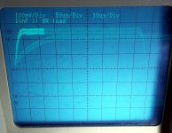
With a rise-time of 50µs, no wonder you see no ringing: you have to excite the amplifier with a stimulus falling into its itching range.
You need a true squarewave generator there too, not a soundcard.
Fortunately, you can make a very good one with just a CD40106 or CD4093, 1 resistor and 1 capacitor.
Based on the decay time of the ringing (the one you will see with a proper square), there must be a mathematical method to derive the phase margin.
Don't ask me for details: you come 40 years too late
I stand corrected: 220pF does make a difference! Didn't see it at first, because it doesn't show at the rising edge... nasty! 100pF seemed to work fine though, couldn't see any oscillations there, while 1nF makes the sine wave scream bloody murder.
Attachments
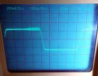
With a rise-time of 50µs, no wonder you see no ringing: you have to excite the amplifier with a stimulus falling into its itching range.
But I wouldn't do that while actually using it as an audio amplifier? The input LPF is supposed to take care of that, no?
Don't ask me for details: you come 40 years too late
I'm not even 40...
EDIT:
Just tested the other circuits with some capacitive loads. All of them start to oscillate with 220pF and more. The standard circuit doesn't go as wild with 1nF, but with 220pF they all ring along pretty much the same.
Last edited:
The purpose of this test is ... testing: if you remain in a quasi-static condition for the amplifier in question, you are going to see nothing, even if it is on the verge of oscillation, and you remarked it yourselfBut I wouldn't do that while actually using it as an audio amplifier? The input LPF is supposed to take care of that, no?
.Just tested the other circuits with some capacitive loads. All of them start to oscillate with 220pF and more. The standard circuit doesn't go as wild with 1nF, but with 220pF they all ring along pretty much the same
If the standard circuit oscillates with 220pF, there is something wrong with the construction: when you arrive at 100nF or more, an inductive zobel might be required, but the circuit should be able to manage low capacitances by itself.
When you venture below the allowed closed-loop gain, anything could happen...
Indeed. My bets would be on insufficient supply bypassing and/or bad layout. (Remember: The layout is the circuit.) OP, mind showing some pictures of the real thing?If the standard circuit oscillates with 220pF, there is something wrong with the construction: when you arrive at 100nF or more, an inductive zobel might be required, but the circuit should be able to manage low capacitances by itself.
The Zobel also seems a bit heavy-handed at 1R||220n - I'd expect maybe 4R7||22-100n.
Of course, but it seems like the same is happening at 27 dB as well, besides I am under the impression that HF gain duly returns to that value in the 6 dB circuit before it finally rolls off.When you venture below the allowed closed-loop gain, anything could happen...
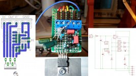
Here's a photo of the test circuit, along with the EAGLE layout and corresponding schematic, in case you want to trace each route exactly. I used some jumpers to easily switch between the different circuit configurations without having to pull out the soldering iron each time.
Power supply is a self-made, adjustable "lab supply" based on LM317 and a tracking LM337, set to +-15V. Bypass caps are 22uF for each rail, bodged directly to the TDA, as can be seen on the photo.
Power supply is a self-made, adjustable "lab supply" based on LM317 and a tracking LM337, set to +-15V. Bypass caps are 22uF for each rail, bodged directly to the TDA, as can be seen on the photo.
Attachments
- Status
- This old topic is closed. If you want to reopen this topic, contact a moderator using the "Report Post" button.
- Home
- Amplifiers
- Chip Amps
- Fun with a cheap TDA2030A at only 6dB gain