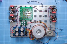
I'm making very slow progress on my 2.1 channel LM3886 & have reached the point where I need to work out the grounding. My previous 2.0 channel LM3886 was essentially permanently ground lifted so I didn't go through this process.
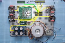
Following the diagram & explanation toward the bottom of this page I think what I need to do is shown in the attached images of my build so far.
Am I on the right track? If so, what is the best physical way to achieve this? Trying to stack 11 crimp connectors onto a single bolt is going to end up a mess, but presumably I can double/triple up wires to crimps?
Also, if I am using shielded cables for the line level inputs to the amps, what should I connect the shield to (if anything)?
Attachments
I think that your 2.1 system will have subwoofer amp bridged, so tehre is no speaker ground for it.
A I correct, if Yes, then you should have only 2 speaker grounds for L & R speaker and for sub you will have wires directly from LM3886 modules (one positive output as +speaker terminal and the other one from positive output as -speaker terminal).
In general your star point is correct.
Maybe in future you will lift your star point with ground lifter (many times suggested in this forum). Mains earth will stay on the metal part of the chassis and star point for all the modules will be on ground lifter side.
Daisy-chaining the power connections like that is a bad idea...each amp needs to to be connected to the power supply separately. All wires have resistance, and the amps down stream from the others will be prone to voltage modulation of the power due to the amps up stream drawing power ahead of them in the circuit. So in effect, what you have there is one amp connected directly to the power supply, the next amp is connected to a power draw through a small value resistor, that amp's power will be affected by the first amp, the third amp will connect through the second amp and the first amp through yet another resistor and will be affected by amps one and two...and even worse for amp number four.
As for your original question...I suggest you read this:
Taming the LM3886 Chip Amplifier – Neurochrome
Tom Christiansen (DIY member) has a very informative and comprehensive article that should help you out.
Mike
As for your original question...I suggest you read this:
Taming the LM3886 Chip Amplifier – Neurochrome
Tom Christiansen (DIY member) has a very informative and comprehensive article that should help you out.
Mike
Last edited:
I think that your 2.1 system will have subwoofer amp bridged, so thre is no speaker ground for it.
Am I correct, if Yes, then you should have only 2 speaker grounds for L & R speaker and for sub you will have wires directly from LM3886 modules (one positive output as +speaker terminal and the other one from positive output as -speaker terminal).
In general your star point is correct.
Maybe in future you will lift your star point with ground lifter (many times suggested in this forum). Mains earth will stay on the metal part of the chassis and star point for all the modules will be on ground lifter side.
It's best to keep all flow and returns close coupled to reduce loop areas and minimise hum pick up, that includes power as well as inputs and outputs. http://hifisonix.com/wordpress/wp-content/uploads/2019/02/Ground-Loops.pdf
I would second both Michael Bean and scottjoplin suggestions.
1. Do not daisy chain power. Bring the power to each amp pcb by a twisted triplet (v+, gnd, v-). Same for the crossover board.
2. Twist the output wires together (speaker out and gnd out) and connect them to the amp pcbs.
3. On the input side, use insulated rca jacks, twist signal and gnd together and bring together to the crossover board. Also use twisted pair between each amp pcb and the crossover board.
4. Ideally, I would use two ground loop breakers. One between the gnd of the amps power supply and the chassis (earth) and one between the crossover power supply gnd and the chassis.
I'm not quite clear on what you're doing with the two amps for the sub. Are you using them paralleled (with a 4ohms driver) or bridged (with a 8ohms driver) ? In the first case, you'll need an inverter before one of the board. In the second case, you'll need high wattage, low value sharing resistors at their outputs. It would also be good to use well matched gain setting resistors.
1. Do not daisy chain power.
I will redo the wiring individually.
Bring the power to each amp pcb by a twisted triplet (v+, gnd, v-). Same for the crossover board.
But should gnd to each amp not be coming from the star ground, rather than from the power supply board?
2. Twist the output wires together (speaker out and gnd out)
Same question, if my speaker ground is coming from the star ground rather than from the amp PCBs (as in the DMS Audio link in the first post)?
3. On the input side, use insulated rca jacks, twist signal and gnd together and bring together to the crossover board.
What about the shield of the cable? Should it be connected to anything, at either end?
I'm not quite clear on what you're doing with the two amps for the sub. Are you using them paralleled (with a 4ohms driver) or bridged (with a 8ohms driver) ? In the first case, you'll need an inverter before one of the board. In the second case, you'll need high wattage, low value sharing resistors at their outputs. It would also be good to use well matched gain setting resistors.
My intention was to parallel them because it's a simpler setup & because the Neurochrome pages recommend against a bridge setup with 2 chips. So I built them with 0.1% gain setting resistors, then was going to measure the DC offsets of all 4 & parallel the two that are closest, through some 3W 0.1R resistors.
However looking into it more now, with my +/-28.5V supply rails & 8Ω sub I will only get ~50W in parallel & it appears that the recommendation against bridging two chips on the Neurochrome page is actually down to the fact that the setup wouldn't support 4Ω operation & would limit supply rails to +/-28V for 8Ω operation. But both of those things are fine for me & would give me a good bit more than 50W.
So is there a simple, community-favoured design for a signal inverter, so I could run a bridged setup instead?
There are a number of ways to do it, for example Bridging Adapter For Power Amps or even this Simplest Ever Bridging Adapter for Amplifiers
The myth of star ground has really grown legs. Perhaps because it's easy to visualize. However, as you've discovered, it's not as easy to execute in practice. I would also argue that star grounding in many cases actually results in worse performance, and doesn't solve the problem it was intended to solve (ground loops).
So here's the deal:
I have long argued (and AndrewT (RIP) before me) that the best ground reference in a single-ended amp is the negative speaker connection. You can see my rationale here: Grounding – Neurochrome
That is actually the perfect example of how star grounding is fundamentally broken. You can see my exploration of various grounding schemes (with measurements) in this thread: LM3886 PCB vs Point-to-Point (with data)
So what to do in your case...
Hope this helps. Best of luck.
Tom
So here's the deal:
- Current flowing through a wire will cause a voltage drop across the wire due to the finite and non-zero impedance (resistance + inductance) of the wire. This is described by Ohm's Law.
- If a significant current flows in a ground reference for the input or feedback of the amp, it will result in an error voltage developed across the reference net. This will degrade amplifier performance.
- Some currents are nice and can be allowed to flow in the ground reference. This includes the return current from the input signal. Current flows in loops, remember? So the signal current that flows into the input impedance, must flow out of the ground reference. That's cool!
- Some currents are not nice as they are heavily distorted. This includes the feedback current. If a distorted current is allowed to flow in the reference net, it will add a distorted error voltage to the input signal, which degrades amplifier performance. So keep that separate - or lump it in with the large currents if you can do so without corrupting the feedback voltage (see next bullet).
- Some currents are large. This includes the current going to the speaker and back through the speaker return. This also includes the power supply currents (that's where the speaker current comes from). Large currents have the potential to cause large error voltages (Ohm's Law again), so they should be kept separate.
I have long argued (and AndrewT (RIP) before me) that the best ground reference in a single-ended amp is the negative speaker connection. You can see my rationale here: Grounding – Neurochrome
That is actually the perfect example of how star grounding is fundamentally broken. You can see my exploration of various grounding schemes (with measurements) in this thread: LM3886 PCB vs Point-to-Point (with data)
So what to do in your case...
- Trust the that the layout engineer did their work correctly.
- Connect the speaker (+) and (-) binding posts to the respective output terminals on the PCB.
- Connect the supply for each amplifier board with three wires directly back to the power supply. Keep these wires tightly bundled as they contain some rather nasty current spikes when the amplifier is running at high output power.
- Connect the input signal and return directly to the RCA jacks. The shell of the RCA jack should be isolated from the chassis. You can use shielded wire if you wish, though generally a twisted pair is sufficient here.
- Connect the power supply ground to the chassis with one wire. That's your system ground reference. If you ever have issues with ground loops, this is the ground connection you lift.
- Connect the mains protective earth to the chassis with a single short wire. It does not have to connect at the same point as the system ground. The mains earth is for safety. The connection to the chassis should be with an appropriate lug and secured by a lock nut. This connection must never be lifted.
- Don't forget to cover all exposed mains connections in heat shrink tubing and to keep a minimum of 6.4 mm (1/4") between any metal connected to the mains live/neutral and the chassis. That's a safety thing.
Hope this helps. Best of luck.
Tom
Nothing much to add to Tom's excellent post. Just a link to Andrew Russell very informative document: http://hifisonix.com/wordpress/wp-content/uploads/2019/02/Ground-Loops.pdf
The wiring layout suggested p.56 is what I'm using and what I designed those boards for.
The wiring layout suggested p.56 is what I'm using and what I designed those boards for.
Thankyou once again everyone for your detailed answers. I finally have some time to work on the amp again & started by re-doing the power wiring as suggested, so that each amp board now has its own dedicated feed rather than the daisy-chain approach I had before.
Reading again the links provided on bridging the sub amp boards, I am drawn to the audio transformer approach as it's just such a delightfully simple solution. Trying to find something suitable from a UK stockist is proving confusing though. I believe what I'm looking for is a 1:1+1 transformer, but failing that can I use this 1+1:1+1 transformer with the mono input signal connected across both primaries in series?
Reading again the links provided on bridging the sub amp boards, I am drawn to the audio transformer approach as it's just such a delightfully simple solution. Trying to find something suitable from a UK stockist is proving confusing though. I believe what I'm looking for is a 1:1+1 transformer, but failing that can I use this 1+1:1+1 transformer with the mono input signal connected across both primaries in series?
Should work just fine, although I might tend more towards the higher impedance -007 (Bond, James Bond) version. Preamps are more likely to be comfortable driving a 2.4 kOhm primary than a 600 ohm one, which would imply having decent headphone driving abilities.
As always with transformers, it's probably a good idea to experiment with RC termination on the secondary (basically, a snubber) to combat ultrasonic ringing.
For optimum distortion performance, you want your driving impedance to be much smaller than primary impedance, i.e. 2.4 kOhms. Not a major issue for typical preamps or soundcard outputs but I wouldn't recommend using a "passive preamp" (= naked volume pot).
The one advantage of using a transformer is that you can easily provide galvanically isolated inputs and thus have an integrated ground loop breaker, should you decide to build the amp as an IEC Class I appliance.
Last edited:
With the coronavirus movement restrictions putting a stop to my other hobbies (drones/RC planes) I'm finally hoping to get this build finished - I think it's been going over 18 months so far!
I've just powered up & listened to the two mid-high modules through the HP filters & they worked as expected, so next I will attempt to bridge the other two modules for the sub. I discovered I already had an unused Neutrik NTE1 transformer in my box of PA parts (it's the part you find in Neutrik's unbalanced RCA to balanced XLR adapters) which I figured I would try even if it is 200 ohm. What would be the telltale indications that the 200 ohm impedance is causing unhappiness?
Also, with regards to the ground reference -
I have two power supplies; the big one for the amp modules (18-0-18 transformer) & the small one for the crossover board (6-0-6 transformer). Do I connect the ground from both of these to chassis ground? This would seem logical to me from the signal side of things, as the signal passes through both the crossover board & the amp boards
I've just powered up & listened to the two mid-high modules through the HP filters & they worked as expected, so next I will attempt to bridge the other two modules for the sub. I discovered I already had an unused Neutrik NTE1 transformer in my box of PA parts (it's the part you find in Neutrik's unbalanced RCA to balanced XLR adapters) which I figured I would try even if it is 200 ohm. What would be the telltale indications that the 200 ohm impedance is causing unhappiness?
Also, with regards to the ground reference -
[*]Connect the power supply ground to the chassis with one wire. That's your system ground reference. If you ever have issues with ground loops, this is the ground connection you lift.
I have two power supplies; the big one for the amp modules (18-0-18 transformer) & the small one for the crossover board (6-0-6 transformer). Do I connect the ground from both of these to chassis ground? This would seem logical to me from the signal side of things, as the signal passes through both the crossover board & the amp boards
Daisy-chaining the power connections like that is a bad idea...each amp needs to to be connected to the power supply separately.
Mike
Star grounding is much better with separate wires to power supply.
In daisy chaining the first amp modulates the ground line which then goes into second amp which modulates the signal.
Star grounding is much better with separate wires to power supply.
In daisy chaining the first amp modulates the ground line which then goes into second amp which modulates the signal.
That's what I said.
Mike
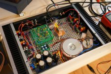
I tried the Neutrik NTE1 but the output from the amp modules to the sub was very low & started to distort really badly as I raised the input level even to only moderate levels. So I ordered the Vigortronix VTX-101-007 to replace the Neutrik part but still had the same issues.
Turns out it's the sub output from the KMTech crossover board which is the issue, as when I connect a low output from my dbx 223XL to the VTX-101-007 the output from the amp modules works as expected - the whole apartment is shaking with nice clean sub.
I can't see anything wrong with the KMTech board, but I think I'm just going to scrap it & stick with an external crossover - it'll give me more flexibility anyway, as I will be able to easily trim the individual channels & also use the amps as regular fullrange amps. I've ordered a new rear panel for the case so I can add another pair of RCA inputs while keeping everything clean. I've had nothing but problems with the KMTech stuff; I've already scrapped both their single LM3886 boards & their parallel LM3886 board which I started this build with...
Attachments
- Status
- This old topic is closed. If you want to reopen this topic, contact a moderator using the "Report Post" button.
- Home
- Amplifiers
- Chip Amps
- 2.1 channel LM3886 star ground questions