Hello to everyone on this site!
My first post here but not my first visit")
I'm a father of two, my first hobby is painting and second is electronics.
(my electronic language is not so good too) please be nice......
A BIG thank you to all for the help and knowledge i received from this site and helped on my project. I want to share it here with you. Started about 2 years ago and still have some work to do.
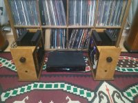
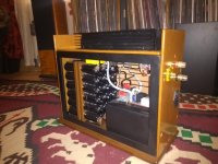
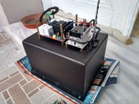
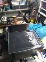
2 monoblocks amplifier based on TDA7293. Started as a joke with spare parts and some cheap PCB from ebay and finished with a total of $1500 (with spare parts). The joke ended when i tested and compared my amplifier on same speakers with Brinkmann Integrated and a Icon Audio Stereo40 MKIII integrated valve amp. There is a long story to explain but in the end my amplifier sounded much better on my ears then other 2. They are 2 monsters of 33kg each. There are 48 x 33000uf/50v each one amp.
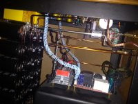
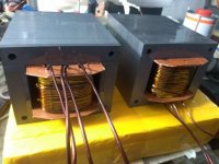
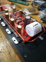
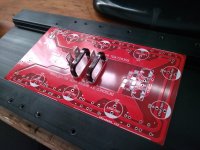
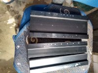
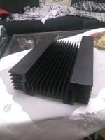
Transformer 21-0-21 (core 14.5cm x 6cm x 4cm, primary wire 0.9 and secondary wire 2.45) All cap connection, vcc+vcc- and basic ground are made with cooper wire 4mmx2mm. All other connection i used solid wire 3mm and 2mm. I designed my own PCB based on heatsink removed from an old burned amplifier. I removed some legs of tda from pcb and used wire on air to make the connections for this legs. Buffer, mute, stand-by, output and removed totally nr 5. Much more space on board for the vcc+ vcc- and more work for my hobby The design is the same as tda datasheet provides except the value changes on C1=5.6uf, C2=470uf, C3,4=100uf, C5=470uf x 8pc.
With this transf. there are ~50w for ic. I believe i have 400w per side on 8 Ohms. Calculation from here: YouTube
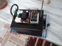
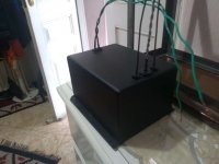
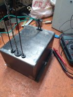
I'm using a start soft from ebay but changed everything (same value but Mouser parts) on board except transformer and relay. No preamp and for the moment i'm using Chinese 2Pole 23 Step Rotary Switch Attenuator Volume Control Pot with Dale resistors 1%. Mdf boards and L iron profile 2.5cm for the case. All parts from Mouser except IN cap Mundorf from HIFI Collective.
Very little noise (fsss) only if i put my ear literally on tweeter.
When i play my aelite 3 looks like the speaker will come in my face and smash me on the wall.
Hope you like this one.....
My first post here but not my first visit
I'm a father of two, my first hobby is painting and second is electronics.
(my electronic language is not so good too) please be nice......
A BIG thank you to all for the help and knowledge i received from this site and helped on my project. I want to share it here with you. Started about 2 years ago and still have some work to do.
2 monoblocks amplifier based on TDA7293. Started as a joke with spare parts and some cheap PCB from ebay and finished with a total of $1500 (with spare parts).
The joke ended when i tested and compared my amplifier on same speakers with Brinkmann Integrated and a Icon Audio Stereo40 MKIII integrated valve amp. There is a long story to explain but in the end my amplifier sounded much better on my ears then other 2. They are 2 monsters of 33kg each. There are 48 x 33000uf/50v each one amp.Transformer 21-0-21 (core 14.5cm x 6cm x 4cm, primary wire 0.9 and secondary wire 2.45) All cap connection, vcc+vcc- and basic ground are made with cooper wire 4mmx2mm. All other connection i used solid wire 3mm and 2mm. I designed my own PCB based on heatsink removed from an old burned amplifier. I removed some legs of tda from pcb and used wire on air to make the connections for this legs. Buffer, mute, stand-by, output and removed totally nr 5. Much more space on board for the vcc+ vcc- and more work for my hobby
The design is the same as tda datasheet provides except the value changes on C1=5.6uf, C2=470uf, C3,4=100uf, C5=470uf x 8pc.With this transf. there are ~50w for ic. I believe i have 400w per side on 8 Ohms. Calculation from here: YouTube
I'm using a start soft from ebay but changed everything (same value but Mouser parts) on board except transformer and relay. No preamp and for the moment i'm using Chinese 2Pole 23 Step Rotary Switch Attenuator Volume Control Pot with Dale resistors 1%. Mdf boards and L iron profile 2.5cm for the case. All parts from Mouser except IN cap Mundorf from HIFI Collective.
Very little noise (fsss) only if i put my ear literally on tweeter.
When i play my aelite 3 looks like the speaker will come in my face and smash me on the wall.
Hope you like this one.....
Attachments
-
 1564843186882.JPEG113.9 KB · Views: 617
 -
 IMG_20191008_153120715.jpg817.7 KB · Views: 576
 -
 IMG_20191008_152957843.jpg742.6 KB · Views: 565
 -
 1563400243076.JPEG74.2 KB · Views: 255
 -
 1562776494990.JPEG99.4 KB · Views: 274
 -
 1558558247411.JPEG67 KB · Views: 304
 -
 9.jpg505.5 KB · Views: 299
 -
 7.JPEG88.8 KB · Views: 356
 -
 5.JPEG104.7 KB · Views: 609
 -
 1.jpg868.1 KB · Views: 562
Last edited:


what a monster! great job!
I would be curious about the schematic, not familiar with tda7293 but nor sure where you got the estimated amp power into 8 ohms . Maybe 400w into 1 ohm...
The transformers are good but I would probably use 25-30v transformers , so around 35-40v dc to take full advantage of the parallel chips .
Why 8 chips /channel? I bet they barely get warm.
what a monster! great job!
I would be curious about the schematic, not familiar with tda7293 but nor sure where you got the estimated amp power into 8 ohms . Maybe 400w into 1 ohm...
The transformers are good but I would probably use 25-30v transformers , so around 35-40v dc to take full advantage of the parallel chips .
Why 8 chips /channel? I bet they barely get warm.
My first attempt was with 28-0-28 ac around 40v dc. the high was not so sweet and clean.
There was some kind of disortion. As datasheed recomend 30v dc i follow that. They was right. I just make the PCB design for 8 IC thinking to change the speakers later with bigger one. Here in the end of the video are calculated the watts of tda :
YouTube
after 4 hours of work the heatsink is about 50.C And the transformer 40.C
There are 400watt/8Ohm of power.
Believe me, you can load 0.5Ohm but, will play much easier the 8Ohm and more easy 16Ohm load then 4Ohm load and less. If i want to have a good HI-FI sound on 2Ohm load you must have a battery or ...lets say 3-4.000.000uF per side.The YouTube video shows you the power for a single chip,
When you parallel chips you will be able to achieve very high power levels into very low impedance , but having 8 ohms impedance will not be a benefit for this amp.
And with good HI-FI sound i have always in mind the test i made with amplifier that cost ~$2000 and ~$4000
Congratulations on an incredible build.
And I bet yours is the largest TDA729x related power supply on the PLANET.
Which definitely must contribute to smooth and solid sound.
Better than other, very expensive amps?
I can agree with that.
Famous Tech Enzo often says: "the amplifier? ... it´s that thingie between the supply and the speaker"
Since the amp is the "faucet" between supply and speaker, having a HUGE "water tank" and HUGE "faucet and pipes" will definitely help to get smoooth clear sound.
Congratulations again.
Only problem I have is ith the 400W into 8 ohm rating, it does not work that way since peak to peak voltage stays the same, whether you use 1, 8, or 64 chipamps in parallel.
But again, the build is IMPRESSIVE.
Congratulations on an incredible build.
Only problem I have is ith the 400W into 8 ohm rating, it does not work that way since peak to peak voltage stays the same, whether you use 1, 8, or 64 chipamps in parallel.
But again, the build is IMPRESSIVE.
The power out of the amp is voltage squared divided by speaker impedance.
So no benefit to paralleled amps into 8 ohms.
But definitely into less than 8 ohms.
Nice build....
First i thank you for the nice word and second, yes you have right.Which definitely must contribute to smooth and solid sound.
It is unbelievable until you listen to it. I started with 60.000 per channel and ended up 1.500.000uF per channel. You just feel there is everything as should be.
From the low freq that can provide a (P) coming from the mouth placed near to the mic and you fill that (P) on entire room to highest plate kick that you just fill it is on the back right of the drummer.
I don't understand the size of the filter caps. 24 x 33mF is 0.8F, which at 10A will droop roughly 0.12Vper mains cycle - you can afford a much faster droop than this, a couple of volts for instance would require only about 47mF of filter cap per rail, one volt droop would require only 82mF
There are 2 rails back to back so 48x33mF = 1,5F per channel.I don't understand the size of the filter caps. 24 x 33mF is 0.8F, which at 10A will droop roughly 0.12Vper mains cycle - you can afford a much faster droop than this, a couple of volts for instance would require only about 47mF of filter cap per rail, one volt droop would require only 82mF
Math and calculation for what value cap is the right one, drop voltage,
mains cycle and etc. are nothing in front of the final result of what you hear coming out from the speakers.
No, under the pcb is only the feedback resistor. Tda is the simplest design i ever see. The design is according datasheet give but for obvious reason i removed the power supply caps.Hi
Congratulations to this build
real TDA - moster
would be interesting how you handled the parts for each TDA chip + the "correction" for paralleling..... i guess its under the pcb?
chris
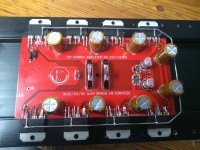
The smd elements you see are only MUTE and STAND BY. Each paralleled tda has only one cap witch can be only one for all if you wish.Pin Nr:5 was removed, Mute, stand by, pin Nr:11 and output Nr: 14 are connected on air with wire 1mm as you see on photo except Nr:14 connected with 3mm wire for the output. When i make the final wiring on the second amp i will try to make some pictures more detailed of pcb.
Hi
would be interesting how you handled the parts for each TDA chip + the "correction" for paralleling..... i guess its under the pcb?
According to the datasheet and in contrary to, let's say, the LM3886, the TDA7293 doesn't need any current balancing resistors in parallel configuration, due to it's DFET power stage.
Anyway, this enormous number of eight devices literally calls for PBTL configuration, hence almost quadrupling output power at the same supply voltages and load impedance. Hints for it also are given in the DS, but it might be better to use a dedicated phase inverter stage with two opamps.
Best regards!
I have been contemplating a cutting amplifier based on a BTL paralleled set of these (maybe 4 + 4 in push pull), but for that application (unlike normal audio) power bandwidth really matters (Due to the inverse RIAA curve there is lots of HF needed), and because the whole mess winds up wrapped in a feedback loop to linearise the mechanics I should really like the power stage to have minimal phase shift until well outside the audio band (No real reason to make stabilising that loop any harder then it already is).
The datasheet is somewhat lacking so, query do you have any numbers on closed loop bandwidth and phase shift for this part?
A Bode plot would be excellent if anyone has one for this device?
Failing that, I will probably draw something CFB but basically straight out of Cordells or Selfs book.
It is a slightly weird application (and possibly a good use for class G) because the peak power is enormous (~500W typically) while the average is at most 10W or so (or you melt the drive coils).
Regards, Dan.
- Status
- This old topic is closed. If you want to reopen this topic, contact a moderator using the "Report Post" button.
- Home
- Amplifiers
- Chip Amps
- 8 x TDA7293(HS) PARALLEL DIY