Hi all!!!
I'm posting after a long time and again I have a query with me. I had made many audio amps using chips coz I just love making it!
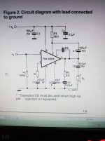
But I have a query bothering me that why the circuits of amps in the datasheets have a resistor connected across the Input pins of the ICs and Ground ? What's their function ?
Another thing I want to know that what's the INPUT IMPEDANCE term mentioned in all chip amps' datasheets ? Is it related to the resistor connected across the Input pin and ground as in the diagram or something else ?
I'm posting after a long time and again I have a query with me. I had made many audio amps using chips coz I just love making it!
But I have a query bothering me that why the circuits of amps in the datasheets have a resistor connected across the Input pins of the ICs and Ground ? What's their function ?
Another thing I want to know that what's the INPUT IMPEDANCE term mentioned in all chip amps' datasheets ? Is it related to the resistor connected across the Input pin and ground as in the diagram or something else ?
Attachments
Hi all!!!
...........................
But I have a query bothering me that why the circuits of amps in the datasheets have a resistor connected across the Input pins of the ICs and Ground ? What's their function ?
Another thing I want to know that what's the INPUT IMPEDANCE term mentioned in all chip amps' datasheets ? Is it related to the resistor connected across the Input pin and ground as in the diagram or something else ?
Hi Arnivan,
Input pins of a chip-amp have a (very small) current going from or to the input pin. The input DC offset voltage is this input current times the DC impedance the input sees externally (+ some bias differences in the input stage).
If you had no such DC impedance (often a resistor) but only looked into a DC separating capacitor with a very high DC impedance, the offset voltage at the input would be very high. Some car amplifier chips actually have this input current compensating impedance integrated in the chip such that only a capacitor is needed at the input (for simplicity).
Further, such a resistor simply ties the amplifier input to signal ground when you have no input source.
An amplifier chip input impedance (data-sheet) is the (equivalent) input impedance of the chip on its own. When you put an external resistor to signal ground, the external resistor and the amplifier input impedance are connected in parallel. You can then estimate the resulting impedance.
Last edited:
I used to use that chip back in 80s for am radio projects ZN414 based as well as Walkman amplifiers. Decent enough sound thru a 5.5" fullrange but not really hi-fi.... there was also published a "labaudio amplifier" using this chip but for mine I plumbed for a couple of Maplin LM1875 application pcbs....
Ah, the trusty TBA820M. For those interested, I went over the circuit details a while back.
BTW, taking a photo of the actual screen has got to be about the silliest way of taking a screenshot ever, just saying. (I didn't write "most cumbersome" because that would involve waiting for the film to get developed and an appropriate scanner.) There's a <PrtScr> (Print Screen) key on your keyboard, and any image editor worth its salt including MS Paint can paste it from the clipboard (<Ctrl>-<V> in that case) and trim things as desired before saving.
BTW, taking a photo of the actual screen has got to be about the silliest way of taking a screenshot ever, just saying. (I didn't write "most cumbersome" because that would involve waiting for the film to get developed and an appropriate scanner.) There's a <PrtScr> (Print Screen) key on your keyboard, and any image editor worth its salt including MS Paint can paste it from the clipboard (<Ctrl>-<V> in that case) and trim things as desired before saving.
I used to use that chip back in 80s for am radio projects ZN414 based as well as Walkman amplifiers. Decent enough sound thru a 5.5" fullrange but not really hi-fi.... there was also published a "labaudio amplifier" using this chip but for mine I plumbed for a couple of Maplin LM1875 application pcbs....
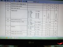
It should be HiFi according to DIN45500 as I recall no power requirements. 2W in 8 Ohm is quite decent. Actually, the human ear is tolerant to much. Today we DIY'ers just smile at such old reminiscences but most untrained ears would hardly notice a difference between that chip and an LM1875 at low power levels and with moderate bass.
...why ... a resistor connected across the Input....
....what's the INPUT IMPEDANCE term mentioned in all chip amps' datasheets....
The naked input of the chip can float to ANY DC voltage. In most cases, we have to force it to halfway between the supply rails; in this one it must be forced "near ground". (There are internal 12k and 6k resistors which then force the halfway voltage.)
This external "bias" resistor has "bias current" in it, which causes a voltage drop. The TYPical 0.1uA bias current times 10,000 makes a 1mV (0.001V) drop, which is "small" for our purposes.
Input Impedance is not on "all" datasheets. This is the naked impedance at the audio input. This chip states "5Meg". So if the external bias resistor is 10k, the effective total is 9.980k. Which is all the same for our purposes.
Hi Arnivan,
Input pins of a chip-amp have a (very small) current going from or to the input pin. The input DC offset voltage is this input current times the DC impedance the input sees externally (+ some bias differences in the input stage).
If you had no such DC impedance (often a resistor) but only looked into a DC separating capacitor with a very high DC impedance, the offset voltage at the input would be very high. Some car amplifier chips actually have this input current compensating impedance integrated in the chip such that only a capacitor is needed at the input (for simplicity).
Further, such a resistor simply ties the amplifier input to signal ground when you have no input source.
An amplifier chip input impedance (data-sheet) is the (equivalent) input impedance of the chip on its own. When you put an external resistor to signal ground, the external resistor and the amplifier input impedance are connected in parallel. You can then estimate the resulting impedance.
But, if a 10K resistor is connected in series with the Input pin then what's the result ?
What film?(I didn't write "most cumbersome" because that would involve waiting for the film to get developed and an appropriate scanner.)

What scanner?
That image was obviously taken with a cellphone and uploaded straight from it.
FWIW even today (I saw it less than an hour ago) there´s people in this very Forum who do not know how to attach an image to a post so best case they paste the direct link but without surrounding it with the tags and worst case copy image and then straight paste it here, as a raw image, in the middle of a text block, which is not recognized .
So it could have been worse :)
But, if a 10K resistor is connected in series with the Input pin then what's the result ?
That depends on to what the other end of the 10K is connected. Typically, it is connected to signal ground and the input is "tied" to signal ground.
Sometime a resistor is connected between an IC input and the signal source in order to bias-current compensate for the resistance seen at the other IC input.
TBA820*M* is a POS compared to the same-ish thing in 14pin staggered-pin DIP package - TBA820*P* or *L*. TBA8** family chip-amps all have high input impedance (circa 2meg); perfect for ceramic-cartridge record players and/or small guitar practice amps (can use Hi-Z tone controls). Grainy sound as you would expect it from your granny's TV set or a desktop radio.
It should be HiFi according to DIN45500 as I recall no power requirements. 2W in 8 Ohm is quite decent. Actually, the human ear is tolerant to much. Today we DIY'ers just smile at such old reminiscences but most untrained ears would hardly notice a difference between that chip and an LM1875 at low power levels and with moderate bass.
Not sure I would equate those old din standards with modern interpretation of hifi. They were "just good enough" specifications for acceptable performance.
... and remember those horrible din plugs someone tried foisting upon us....
Not sure I would equate those old din standards with modern interpretation of hifi. They were "just good enough" specifications for acceptable performance.
... and remember those horrible din plugs someone tried foisting upon us....
I agree with you that the old HiFi standard (DIN45500) is not describing the performance level today. But, "HiFi" was explicitly stated and it is the latest (and perhaps only) "HiFi" standard. It appears that they later tried to make a modern HiFi standard but ran into that the human perception of natural sound is so individual and cannot reasonably be expressed in technical terms. They made audio test guidelines instead.
My point is that even old circuits that comply with the DIN45500 will still today satisfy many ears. Ask the vacuum tube guys.
My sentiments precisely - and yes! I am Valve audio listener too. It might be of interest one day to revist those small "chipamps" perhaps with a good quality high sensitivity speaker design. You're right the spec wasn't bad for the time nor overall, really. The one thing I remember is blowing up at least 3 TDA820s trying to get more bass!
Bass dosent live in a DIP package....
trying to get more bass!
...
Bass dosent live in a DIP package.
Yes, you just didn't look well. It is hidden inside near the rear surface.
After hearing what I could get out of a PAM8403 (even smaller than a DIP package) with a 5V supply, I believe many DIY starters should do something very simple as a first project and get some valuable but very cheap experience before going to something complex.
I think the idea of trying to get the output stage to charge 10,000uF of output cap may have caused their premature demise. That and the fact it was the speakers that were really lacking. This was my initial attempts at audio electronics ��
We all did things in the early days we would not repeat today. I used in my young days to make physically big speakers with a number of full-range drivers all connected in parallel. I had no consideration for the impedance and how the amplifier was sweating to drive them. Electronic DIY without occasionally doing something stupid is hardly possible.
A-ha ... that's where the magic smoke comes out! It comes out with the bass!...
Yes, you just didn't look well. It is hidden inside near the rear surface.
...
You cheat! That chip is a SOP/SOIC! ... But this further validates my claim that the bass dosent live in A DIP ......
After hearing what I could get out of a PAM8403 (even smaller than a DIP package) with a 5V supply,
...
- Status
- This old topic is closed. If you want to reopen this topic, contact a moderator using the "Report Post" button.
- Home
- Amplifiers
- Chip Amps
- Tba820 amplifier