Sounds good. We are waiting impatiently for the results.
Bonne nuit!
Hello again..
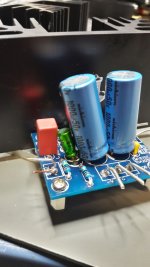
so the first 20 hours are done. i am actually happy with this configuration. i know the caps from other project and i am once again very satisfied with the sound of these green monsters
")
here is a album (little bit strange
..)where i found no bloated bass anymore with my sonus faber venere 1.5 (stand 1,3m before the back wall and 90 cm before the side wall) the control is now how i like it. i played this 6R speakers nearly between 10-25W now..chris
Attachments
Hi
the red 10µ 16V electrolytic cap is definitively junk!
last pic at 10hz
chris
Geee ! who woulda thought? Curious part is your actually using it.
Hello again..
so the first 20 hours are done. i am actually happy with this configuration. i know the caps from other project and i am once again very satisfied with the sound of these green monsters
here is a album (little bit strange
chris
Well done, Chris.
Both the green 10uF and 100uF capacitors are Nichicon bipolar types?
If no more bloated bass, how does the amplifier in general sound on your Sonus Faber?
Better or worse than TPA3250?
Well done, Chris.
Both the green 10uF and 100uF capacitors are Nichicon bipolar types?
If no more bloated bass, how does the amplifier in general sound on your Sonus Faber?
Better or worse than TPA3250?
hi FF
Yes the ES are bipolar caps. if you look at neurochrome - he use it too ....
i use them for my recovery at my 28years old Accuphase C200v and at my TPA3255 amps. i tried other bipolar e.g. the small blue from panasonic no chance - they are hard in sounding, normal polar elna silmic 2 are a save cap. i am sorry but foil caps i have nearly nothing at home...
i will do a compare between my TPA3250 and my "fake amp" after some extra hours running the ES caps.
chris
Geee ! who woulda thought? Curious part is your actually using it.
Hi Bare
yes i know but i try a bit science
i measured some used junk caps from the kit and original used caps. capacity and ESR is the main difference - the ESL is nearly the same
chris
Attachments
Well done, Chris.
Both the green 10uF and 100uF capacitors are Nichicon bipolar types?
If no more bloated bass, how does the amplifier in general sound on your Sonus Faber?
Better or worse than TPA3250?
Good evening
As "requested" by FF i did a SQ compare between my actual 1875amp1_2 (green caps) and my modded TPA3255 (fake amp) and my mod FX502spro (TPA3250).
at my sonus faber venere 1,5 - this are in my aspect "sounded" because the bass has a hump about 6 db in low frequency.
well the Class D chips are very similar and sometimes i think the small one FX502spro is better but if i switched to the "big" amp (TPA3255) it shows the small one were the direction should go. the TPA3255 is in every aspect smart and dead quiet, the dynamic is 1 step ahead the small amp.
so what about the LM1875? the bass is not bloated anymore -its a fine strong and deeper bass- i mean the bass drums are a bit bigger but the skin is not so tight as the other amps - but with the venere maybe not the ideal partner.
the mid and high are excellent - i never hear today a bad , t, th, s, z from the LM1875... plus the male voice get and extra honey (e.g. Udo Schild / album I´m still waiting).....very enjoyable if you thing what i have to invest at the class D amp to avoid this !!!
what i miss is the sound stage in width and deepness
the attention to hear more about the rear area and deep left/right cost some "points". i am still not happy with the "noise" - i try to explain : if you breath slow through your nose - this sound is existing from the amp in the background -so this fog avoid the clearness from deep and width.maybe a much better supply ripple will help - or the THD and the PSSR is the "main reason"???
so it is still a very fine amp...and I am not finished with this chip amp.
chris
Good evening
As "requested" by FF i did a SQ compare between my actual 1875amp1_2 (green caps) and my modded TPA3255 (fake amp) and my mod FX502spro (TPA3250).
at my sonus faber venere 1,5 - this are in my aspect "sounded" because the bass has a hump about 6 db in low frequency.
well the Class D chips are very similar and sometimes i think the small one FX502spro is better but if i switched to the "big" amp (TPA3255) it shows the small one were the direction should go. the TPA3255 is in every aspect smart and dead quiet, the dynamic is 1 step ahead the small amp.
so what about the LM1875? the bass is not bloated anymore -its a fine strong and deeper bass- i mean the bass drums are a bit bigger but the skin is not so tight as the other amps - but with the venere maybe not the ideal partner.
the mid and high are excellent - i never hear today a bad , t, th, s, z from the LM1875... plus the male voice get and extra honey (e.g. Udo Schild / album I´m still waiting).....very enjoyable if you thing what i have to invest at the class D amp to avoid this !!!
what i miss is the sound stage in width and deepness
maybe a much better supply ripple will help - or the THD and the PSSR is the "main reason"???
so it is still a very fine amp...and I am not finished with this chip amp.
chris
Hi Chris,
Many thanks for the detailed comparison analysis. For the LM1875, no more bloated bass but high quality mid and treble.
LM1875 became very popular among more conservative users appreciating jazz, chamber music and other classical music, folk music, acoustic music etc. where the reproduction of acoustic instruments and vocals is important. That fits well with your findings. LM1875 should also be suited for the satellite speakers in a 2.1 system.
With moderate power, LM1875 is less obvious for the type of modern music in which bass is a crucial element. I noticed that your taste in music is quite varied, probably with a preference for analytic recordings.
You describe some fine details in the LM1875 sound you find are not the best. Exactly which technical parameter that may be linked to such sound characteristics, I do not know. One characteristic of class AB is that the sound of the amplifier changes more with the operating circumstances than for class D. Such operating circumstances are in particular supply voltage level and amplifier gain.
If I recall right, you have a nice double and variable power supply. I will propose you to try that power supply with the LM1875. The regulated supply voltage will have very little ripple and the sound characteristics may change with the supply voltage level. Also the gain (min. 20dB) may change the sound characteristics.
From your results, I have now ordered Nichicon Muse capacitors as well.
I got the cheap IRS2092 mono-board for just below 14 Eur. I bought only one as I will use it for test and eventually a sub-channel.
Last edited:
Hi FF
yes the LM1875 is a very fine sounding amp.
if you mentioned my lab power supply-yes this should be less ripple but the fan´s are really loud and its not for listening.
yes i like analytical and very important - good sound stages . this gives me the "live" feeling at home...and once again: with music like Blank&Jones album "relax edition 4" = electronic this amp sounds very good and the power is really enough for at home to shake the house
testing with other speakers - my kef Q100, open baffle 12/5
i am still hoping to get better sound out of the 1875 -
- PSU - less ripple as possible
- check all original kit components
- set the gain down - what should i do?
- PSRR is at the neg.supply worse - frequency depending (figure 7 ) is here something to "help" the chip ?
to be honest - yes if you look at the data sheet you see what that chip can compared to the others.(attachment) i know that its partly nonsense to buy a kit about 2 € add some components (+6€) and expected a fantastic sound but that for me the target to squeeze that out -that´s my personal mind setting.
chris
yes the LM1875 is a very fine sounding amp.
if you mentioned my lab power supply-yes this should be less ripple but the fan´s are really loud and its not for listening.
yes i like analytical and very important - good sound stages . this gives me the "live" feeling at home
...and once again: with music like Blank&Jones album "relax edition 4" = electronic this amp sounds very good and the power is really enough for at home to shake the housetesting with other speakers - my kef Q100, open baffle 12/5
i am still hoping to get better sound out of the 1875 -
- PSU - less ripple as possible
- check all original kit components
- set the gain down - what should i do?
- PSRR is at the neg.supply worse - frequency depending (figure 7 ) is here something to "help" the chip ?
to be honest - yes if you look at the data sheet you see what that chip can compared to the others.(attachment) i know that its partly nonsense to buy a kit about 2 € add some components (+6€) and expected a fantastic sound but that for me the target to squeeze that out -that´s my personal mind setting.
chris
Attachments
@IRS2092 amp
please write your findings to the IRS2092 thread.
200W IRS2092 Amp for $20
here are some links to read:
Tips and suggestions on IRS2092 implementation?
My design L20D IRS2092+IRFI4020H 200W8R
chris
please write your findings to the IRS2092 thread.
200W IRS2092 Amp for $20
here are some links to read:
Tips and suggestions on IRS2092 implementation?
My design L20D IRS2092+IRFI4020H 200W8R
chris
Hello guys,
Sorry for off-topic, but I see no other option other than to post here: I tried to send a Private message to a member FauxFrench, but I couldn't, saying that his inbox is full and cannot accept more messages. So, FauxFrench, if you are reading this, please let me know, as I'd like to contact you. Thanks
And now my 2 cents on topic: of all "LM-Gainlone" iterations I have tried, the most pleasing to me was the tube buffered one, with inverting input, big EI transformer and small capacitors (1000 uF per rail).
Class D, I have tried tpa3116 but it sounded a bit thin and harsh on my ears...
Regards,
Vix
Hi FF
yes the LM1875 is a very fine sounding amp.
if you mentioned my lab power supply-yes this should be less ripple but the fan´s are really loud and its not for listening.
yes i like analytical and very important - good sound stages . this gives me the "live" feeling at home
testing with other speakers - my kef Q100, open baffle 12/5
i am still hoping to get better sound out of the 1875 -
- PSU - less ripple as possible
- check all original kit components
- set the gain down - what should i do?
- PSRR is at the neg.supply worse - frequency depending (figure 7 ) is here something to "help" the chip ?
to be honest - yes if you look at the data sheet you see what that chip can compared to the others.(attachment) i know that its partly nonsense to buy a kit about 2 € add some components (+6€) and expected a fantastic sound but that for me the target to squeeze that out -that´s my personal mind setting.
chris
Hi Chris,
Your chip-amp comparison scheme shows your very systematic approach to development. A good way to get an overview. But, I believe your are not fully fair to the TDA7265 on THD (8 Ohm) where you use a worst case value: https://www.google.fr/url?sa=t&rct=j&q=&esrc=s&source=web&cd=1&ved=2ahUKEwiqgI7im6_lAhW88uAKHcYzCWsQFjAAegQIABAC&url=https%3A%2F%2Fwww.st.com%2Fresource%2Fen%2Fdatasheet%2Ftda7265.pdf&usg=AOvVaw0GxWyDI_C6Vf5Qhrhp0d2z
I read values of 0.01% and 0.02% for 8 and 4 Ohm loads.
It makes a lot of sense to start with a very cheap kit and see what you can get out of it. When you finish your LM1875 work, I guess you will agree that the sound is in the better half of what is sold as commercial products, disregarding price. That we can get surprisingly much out of very little (economically seen) is what may inspire youth to continue this intellectual challenge. Did we just end up with a mediocre result, it would be a futile effort. For too long we have gotten into the habit of just buying without caring much about what we get and actually need. I guess you will agree that your perspective changed when you, as a prior audiophile, entered DIY electronics and got an idea how the circuits influence the sound.
As I have a temptation for re-use, I have a number of dual-winding power transformers recovered from old scrapped amplifiers. I then buy (or even recover) good size electrolytic capacitors of decent quality to make unregulated power supplies. To those unregulated power supplies, I add separate (variable) regulator boards typically based on buffered LM317/337. As result, I have silent variable (dual-) voltages with little ripple and surge current capability in the order of 10A. The whole lot does not look pretty but is very useful for testing of amplifiers (single- or dual supply) and didn't cost me much.
Changing the gain of the LM1875 is with R4 (20K) on page 2 of the datasheet: http://www.ti.com/lit/ds/snas524a/snas524a.pdf
I dare not say how much the power supply ripple influences the fine sound details you analyze.
Last edited:
Hi
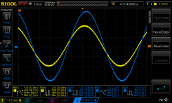
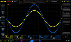
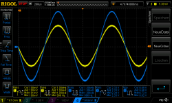
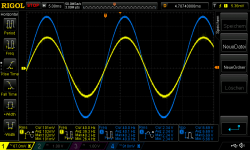
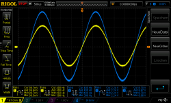
something without sound i made some frequency response test on 8R to look at my actual amp1_2 (green caps) at the low level and this phase shift.
the phase shift is still visible - any ideas to that??? 1k is ok. lower freq. are "earlier" and higher as 1k, 20k... its "later"
so different frequencies go with a different phase /time to the output?
yellow 100Vrms in and the blue is on the R channel output terminals
40hz, 100,400,1k,6k,12k, 20k,30k
chris
something without sound
i made some frequency response test on 8R to look at my actual amp1_2 (green caps) at the low level and this phase shift.the phase shift is still visible - any ideas to that??? 1k is ok. lower freq. are "earlier" and higher as 1k, 20k... its "later"
so different frequencies go with a different phase /time to the output?
yellow 100Vrms in and the blue is on the R channel output terminals
40hz, 100,400,1k,6k,12k, 20k,30k
chris
Attachments
Last edited:
Hi
something without sound
the phase shift is still visible - any ideas to that??? 1k is ok. lower freq. are "earlier" and higher as 1k, 20k... its "later"
so different frequencies go with a different phase /time to the output?
yellow 100Vrms in and the blue is on the R channel output terminals
40hz, 100,400,1k,6k,12k, 20k,30k
chris
Hi Chris,
Such phase shift is normal. It relates to phase lead- and lag networks. I will not claim to be a specialist in this but until more clever people comment, I will give you a hint.
At low frequencies you seem to have a phase lead phenomenon with the output phase preceding the input phase. My impression is that it relates to the two Nichicon Muse capacitors that cause a lead effect at low frequency where the capacitors have an influence.
At high frequencies you seem to have a phase lag effect with the output phase succeeding the input phase. My guess is it relates to either the inherent phase-lag of the amplifier circuit itself or to the zobel network.
Last edited:
...phase shift with the other board - amp2
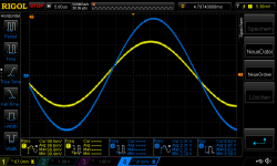
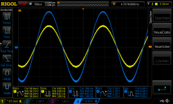
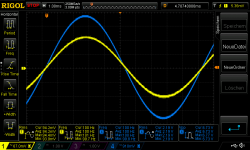
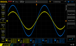
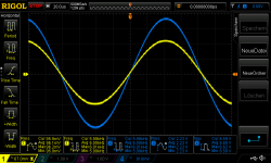
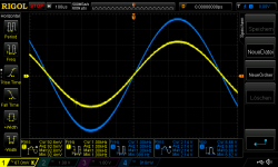
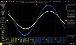
Hi
i did this phase shift measurements on the other board (wima 4,7µ, 22µ ES green muse NFB - huge 1000µF caps at the rails)
yellow 100Vrms in and the blue is on the R channel output terminals
40hz, 100,400,1k,6k,12k, 20k,30k
chris
Hi
i did this phase shift measurements on the other board (wima 4,7µ, 22µ ES green muse NFB - huge 1000µF caps at the rails)
yellow 100Vrms in and the blue is on the R channel output terminals
40hz, 100,400,1k,6k,12k, 20k,30k
chris
Attachments
-
 30k_amp2.png50.5 KB · Views: 42
 -
 20k_amp2.png48.6 KB · Views: 38
 -
 12k_amp2.png49.3 KB · Views: 37
 -
 6k_amp2.png49.4 KB · Views: 37
 -
 1k_amp2.png49.1 KB · Views: 41
 -
 400_amp2.png52.7 KB · Views: 42
 -
 100_amp2.png49.8 KB · Views: 48
 -
 40_amp2.png53.4 KB · Views: 44
 -
 4µ7wima22µES_1000µFrail_1.jpg214.4 KB · Views: 74
Hi
i did this phase shift measurements on the other board (wima 4,7µ, 22µ ES green muse NFB - huge 1000µF caps at the rails)
yellow 100Vrms in and the blue is on the R channel output terminals
40hz, 100,400,1k,6k,12k, 20k,30k
chris
Am I right, there is little difference with the other board?
...cap bank ..capacity check...resistor too high.
Good evening
i really thinking about the capacity at my amp and the ripple. therefore i did a check with my LCR meter to "see" the max capacity per rail at my mock up.now with the amp1_2 (ES caps)
remember i have -per rail per amp side:
2x100µF at the board
3300µF directly mounted on the terminal of the board
1x1000µF at the cap bank
0,4 R
and then the 2x2200µF-which is the first after the rectifier
200+3300+1000+4400=8900 with tolerance less - i measured 7,5mF so ok or not?
why i do not see with the LCR the other caps to the other amp side? missing
200+3300+1000= 4500µ --> 13400µF per rail ideal
after searching around i found the problem --> the 0R4 is too high the LCR can´t see the caps at the other side. i soldered a 0R1 in parallel to the 0R4 and i did the same measurement agian- now i see 11,6mF a the complete rail. i checked this from the other side too.
a test at 200mVrms 1khz input on 8R load to look at the ripple - 04R and 0R1//0R4 - differential probe
measuring point is at after the rectifier
measuring at the cpa bank last cap
directly on the amp board terminal (where the 3300µF caps are)
add the 0R1
measuring point is at after the rectifier
measuring at the cpa bank last cap
directly on the amp board terminal (where the 3300µF caps are)
technicaly its getting a little bit worse..sound check not done...
dont ask me why the 100hz ripple signal is scattered
chris
Attachments
-
 changed 0R1_after rectifier_8R_v5.png53.9 KB · Views: 44
 -
 directly at the amp board_8R_v41.png55.8 KB · Views: 36
 -
 after R_psu board out_8R_v41.png53.9 KB · Views: 44
 -
 after rectifier_8R_v41.png51.1 KB · Views: 72
 -
 changed 0R1_R_psu board_8R_v5.png53.6 KB · Views: 44
 -
 changed 0R1_directly at the amp board_8R_v5.png53.8 KB · Views: 43
Last edited:
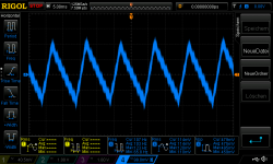
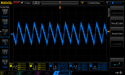
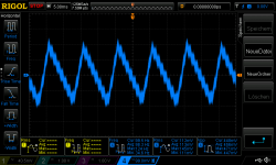
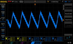
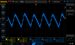
......dont ask me why the 100hz ripple signal is scattered
chris
OK, we don't ask..........
"Scattered", do you mean the sine-wave signal modulated on top of the saw-tooth signal? If so, isn't it the consumption of the amplifier that causes the sine-wave?
Am I right, there is little difference with the other board?
yep...you are the expert...explain me
do not use a too small heat sink at 4R...thermal protection kicks in
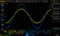
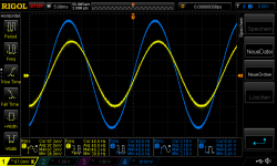
Hi
i try my phas shift test at 4R with the200VRMS 1khz tone . but during measruring at the rail a feel/smell the heat of the poor guy = Lm1875
output signal = 200Vrms in - out 13Vpp at 4R its about 5,2 WATT
rail ripple - 2 pics
thermal protection - every 4 sec lm1875 try again.. 82 °C
so please do not do that with a heatsink of 2,3k/W !! if you look at the datasheet - figure 9 - if you request 5 W the LM1875 has to dissipate with a rail of 25V abut 22WATT heat !!
the test was 2 hours ago...so now its playing fine...LM1875 is a robust chip
chris
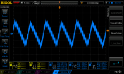
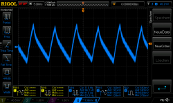
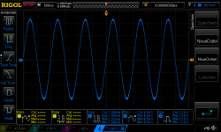
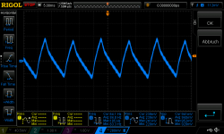
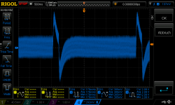
Attachments
- Home
- Amplifiers
- Chip Amps
- eBay mono LM1875 kit