The 0R1 resistors reduce high order harmonics from the rectifier and mains and the DC waveform is much cleaner (quoted from source).
Chris
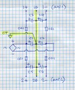
I've added a schematic of the power supply to clarify my comment. You wanted to use the FC closest to the transformer, so they would be C1, C2 and the FW would be C3, C4, C5, C6.
I'm only an amp builder and have picked up this stuff over the decades but I do not pretend to understand it. Hugh Dean (AKSA) has tried to explain this stuff to me but it just shoots over my head. My expertise is in speaker design and build.
Chris
I've added a schematic of the power supply to clarify my comment. You wanted to use the FC closest to the transformer, so they would be C1, C2 and the FW would be C3, C4, C5, C6.
I'm only an amp builder and have picked up this stuff over the decades but I do not pretend to understand it. Hugh Dean (AKSA) has tried to explain this stuff to me but it just shoots over my head. My expertise is in speaker design and build.
Attachments
not ready...
Hi
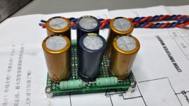
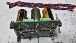
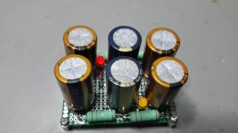
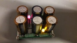
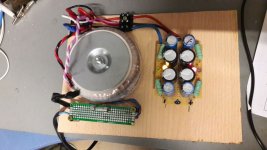
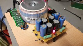
as promised..pics from the dual supply with 1 cap bank. the blue caps in the middle will be connected to the rectifiers +/- pole. the gold caps are for each amps and each side i get the +25V - 0 - -25V. i plan to solder the wires under the pcb red-black-blue on each side
R = 0,2R/5W...from my stock..
chris
Hi
as promised..pics from the dual supply with 1 cap bank. the blue caps in the middle will be connected to the rectifiers +/- pole. the gold caps are for each amps and each side i get the +25V - 0 - -25V. i plan to solder the wires under the pcb red-black-blue on each side
R = 0,2R/5W...from my stock..
chris
Attachments
Hi
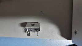
i have on hand a KBPC604. so its rated for 400V and 4Amps..but i am sure its too small = 4 Amps is too less current..
https://www.vishay.com/docs/93585/vs-kbpc1series.pdf
i have on hand a KBPC604. so its rated for 400V and 4Amps..but i am sure its too small = 4 Amps is too less current..
https://www.vishay.com/docs/93585/vs-kbpc1series.pdf
Hi
as promised..pics from the dual supply with 1 cap bank. the blue caps in the middle will be connected to the rectifiers +/- pole. the gold caps are for each amps and each side i get the +25V - 0 - -25V. i plan to solder the wires under the pcb red-black-blue on each side
R = 0,2R/5W...from my stock..
chris
Looks good. Don't forget the transformer CT has to go in at the centre blue caps.
ESP recommends a 10A minimum bridge rectifier. I used 35A on my 120VA 18-0-18 transformer but I did use a 6A on my small 20VA 15-0-15 transformer supply but did add a heatsink to it in case. It never got warm during tests.
Thanks rabbitz - i am looking for one phase 10A rectifier
Looks good. Don't forget the transformer CT has to go in at the centre blue caps.
yep Sir !
")
small step forward
Good evening
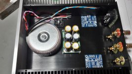
here some pics from a small step forward.
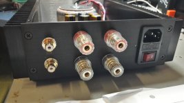
transformer mounted, speaker terminal, rca terminal, power socket with switch,
rectifier mounted
the rectifier is a diotech KBPC 2504....25A version with alu bottom plate- it was the only version which was today available
my cap board gets 2 leds = red for +25V and yellow for the -25V
chris
Good evening
here some pics from a small step forward.
transformer mounted, speaker terminal, rca terminal, power socket with switch,
rectifier mounted
the rectifier is a diotech KBPC 2504....25A version with alu bottom plate- it was the only version which was today available
my cap board gets 2 leds = red for +25V and yellow for the -25V
chris
Attachments
Good evening
here some pics from a small step forward.
transformer mounted, speaker terminal, rca terminal, power socket with switch,
rectifier mounted
the rectifier is a diotech KBPC 2504....25A version with alu bottom plate- it was the only version which was today available
my cap board gets 2 leds = red for +25V and yellow for the -25V
chris
Chris, it just looks really good as always.
The blue amplifier PCB boards, are they for guaranteed genuine LM1875s where the seller has to state on his honor that they are not fake?
You and your son made some Amazon and AliExpress LM1875 boards. Did you actually listen to those amplifiers?
I am looking forward to hear what you think of LM1875 sound. It must be your first class AB DIY amplifier.
Good Morning FF
thanks for the roses...
the sellers (aliexpress or amazon) do not stated that this chips are original. this was the reason why i burn 1 chip from aliexpress and 1 chip survied from amazon.
no i do not listening to this amplifier up to know because i do not have build the psu and trani etc. at a test board. sound-wise i expect a similar listening level of a tuned TDA7498...i got and ready amp and i changed the filter and the gain.
yes this is my first DIY class AB amp i choose the lm1875 because of its good thd and freqency response in the upper high...compared to the stronger brothers e.g. tda729x or your nice TDA7265. your amp (tda7265) was the initial trigger to start with AB chip....thanks for that...
chris
thanks for the roses...
the sellers (aliexpress or amazon) do not stated that this chips are original. this was the reason why i burn 1 chip from aliexpress and 1 chip survied from amazon.
no i do not listening to this amplifier up to know because i do not have build the psu and trani etc. at a test board. sound-wise i expect a similar listening level of a tuned TDA7498...i got and ready amp and i changed the filter and the gain.
yes this is my first DIY class AB amp
i choose the lm1875 because of its good thd and freqency response in the upper high...compared to the stronger brothers e.g. tda729x or your nice TDA7265. your amp (tda7265) was the initial trigger to start with AB chip....thanks for that...chris
psu test board
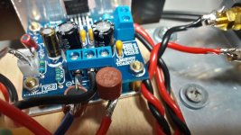
Hi
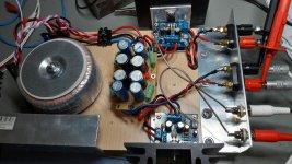
i pick up the idea by FF to have something to listening - so I start to build a psu test board. I use what i had at home.
first the good news...it was the first time to build a psu....nothing explode or get damaged
3,15 A primary fuse....120VA 18-0-18 transformer (sedlbauer) same rectifier 25A - cap bank is 4x 2200µF is the first cap after the rectifier - then to each side a 0,3R and the blue caps are just 1000µ /50V nichicons
values
without cap bank - trani + rectifier bridge ....20,2VAC each winding - after rectifier 18,7V DC each- so the diodes "eats" about 0,75V each
with cap bank 20,4AVC each winding - after rectifier measured on the ouputs of the cap bank 27,2V Dc without load
amp board:
so just build a fuse board to each side of a amp - amp board mounting + speaker connection and rca inputs...
chris
Hi
i pick up the idea by FF to have something to listening - so I start to build a psu test board. I use what i had at home.
first the good news...it was the first time to build a psu....nothing explode or get damaged
3,15 A primary fuse....120VA 18-0-18 transformer (sedlbauer) same rectifier 25A - cap bank is 4x 2200µF is the first cap after the rectifier - then to each side a 0,3R and the blue caps are just 1000µ /50V nichicons
values
without cap bank - trani + rectifier bridge ....20,2VAC each winding - after rectifier 18,7V DC each- so the diodes "eats" about 0,75V each
with cap bank 20,4AVC each winding - after rectifier measured on the ouputs of the cap bank 27,2V Dc without load
amp board:
so just build a fuse board to each side of a amp - amp board mounting + speaker connection and rca inputs...
chris
Attachments
Last edited:
Right Chris, I normally test the whole system before I eventually bother to do the time (and money) consuming job of putting the lot in a nice chassis.
As you show, a mock-up can quickly be made and tests made that all work as assumed. Occasionally it may not work as expected and it is much better to know before you have arranged all the elements in a nice chassis. Then, you can make the necessary modifications and subsequently arrange the system that works in the chassis.
Evidently with such an open structure, you have to be very careful with high voltage access and you may have a bit of hum that disappears in the final metallic chassis.
Right Chris, I normally test the whole system before I eventually bother to do the time (and money) consuming job of putting the lot in a nice chassis.
As you show, a mock-up can quickly be made and tests made that all work as assumed. Occasionally it may not work as expected and it is much better to know before you have arranged all the elements in a nice chassis. Then, you can make the necessary modifications and subsequently arrange the system that works in the chassis.
Evidently with such an open structure, you have to be very careful with high voltage access and you may have a bit of hum that disappears in the final metallic chassis.
Hi FF
yes this mock up is fine for more testing and yes you are right...the 230VAC in the near of my left arm is not safe !
20 year ago i repair a turntable and forgot to disconnet the 230AC
...i dont like itchris

update....amp board...test ok..
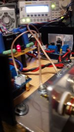
Hi
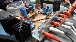
i finalized my mock up and every thing is as tight as my planned amp housing.
the 230VAC area is now protected!
with amp board and a 50mV sweep (10hz - 35khz) i got stable rail voltage of 27,2V if i push 100mV no change on the rails.
no on off pop on both channels...fine
burn in with 50mV or 70mV or 100mV since 2 days...no problem now.
what i do not like is my small heat sink (2,3K/W) - during the test i got about 58°C on the chip with 1 hour 100mV input - its about 1 Watt or so into 8R
the connection from the polished alu bracket to the heat sink is not ok -it has to be more then 1 screw...and i forgot to install a fuse for the amp boards (2,5A fast)
i am afraid to connect good speakers....so no listening test up to know. my lab speaker visaton FR 8 3,3 "- give me no hum or strange noise..so this give me hope
chris
Hi
i finalized my mock up and every thing is as tight as my planned amp housing.
the 230VAC area is now protected!
with amp board and a 50mV sweep (10hz - 35khz) i got stable rail voltage of 27,2V if i push 100mV no change on the rails.
no on off pop on both channels...fine
burn in with 50mV or 70mV or 100mV since 2 days...no problem now.
what i do not like is my small heat sink (2,3K/W) - during the test i got about 58°C on the chip with 1 hour 100mV input - its about 1 Watt or so into 8R
the connection from the polished alu bracket to the heat sink is not ok -it has to be more then 1 screw...and i forgot to install a fuse for the amp boards (2,5A fast)
i am afraid to connect good speakers....so no listening test up to know. my lab speaker visaton FR 8 3,3 "- give me no hum or strange noise..so this give me hope
chris
Attachments
Last edited:
- Home
- Amplifiers
- Chip Amps
- eBay mono LM1875 kit